History of the Atlantic Cable & Undersea Communications
from the first submarine cable of 1850 to the worldwide fiber optic network

Cables and Core Sections, 1875-1912

Introduction: This page features a group of nine cable samples – two recovered cable pieces and seven sections of cable core (the copper conductor with its gutta percha insulation) – which illustrate some changes in submarine cable design in the fourth quarter of the 19th century.

According to site visitor Lloyd Eadline, these were at one time in the collection of Merritt’s Museum in Douglassville, Pennsylvania. There is no record of how or when the museum acquired the cable sections, but they had been kept in a box in storage and were never on display. The museum closed in 2005 and its contents were sold at auction, so it is very unlikely that any further details of their provenance will ever be known.

Some years before the closure, Lloyd’s late father, Herbert S. Eadline (1919-2012), had performed some restoration work for the museum and for the adjoining Doll Museum, and he was given the box of cables at that time. In May 2020 Lloyd decided that the cables needed a new home where they could be used for research and education, and very kindly arranged their transfer to the Atlantic Cable website, where they are shown and described on this page in memory of Herbert Eadline.

—Bill Burns

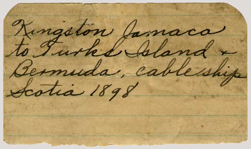
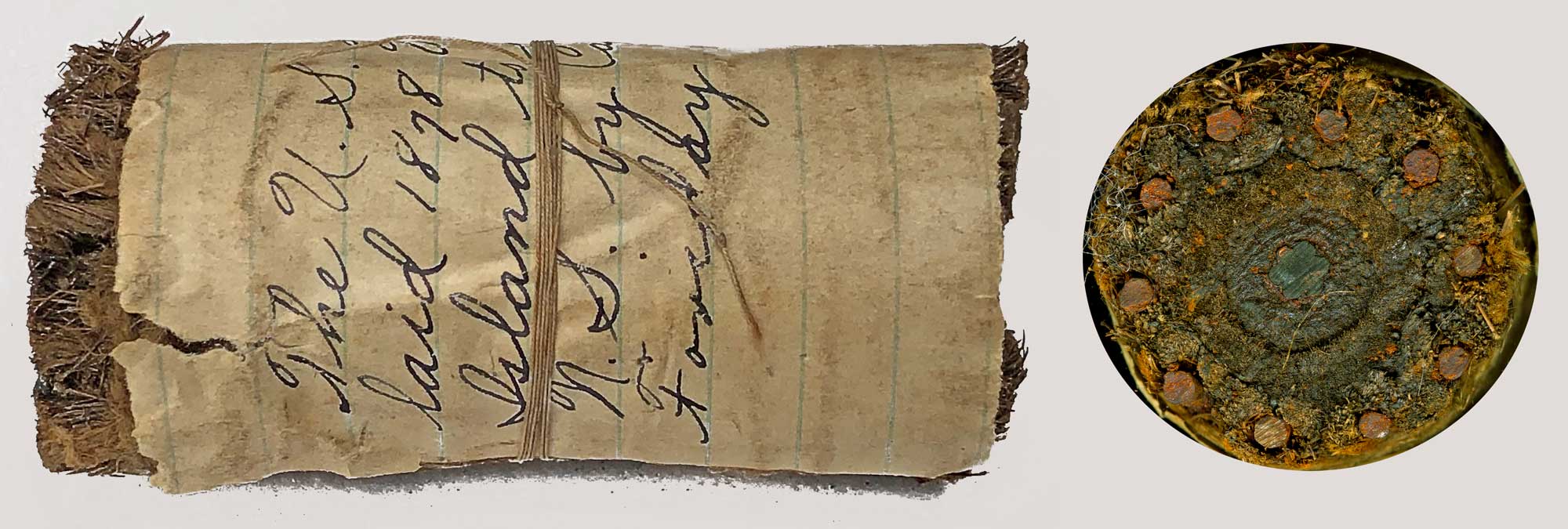
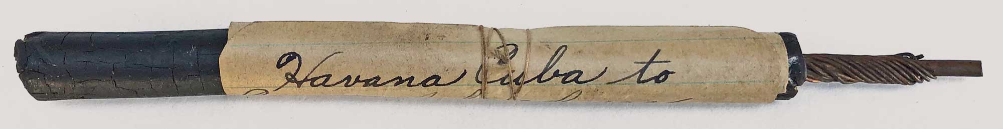
Notes: Each of the nine specimens has an old handwritten paper label wrapped around it, secured with thin twine on some of the sections. While the labels are useful in helping establish which cable each section came from, in some cases they contain inaccuracies or misspellings. The cable sections are listed below in chronological order based on dates and other information on the labels.

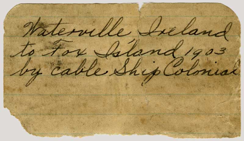
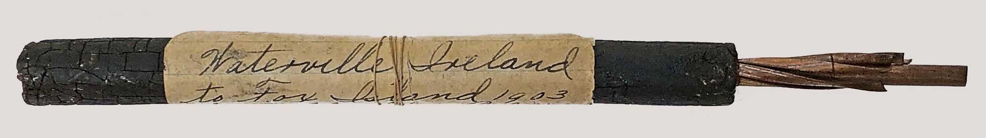
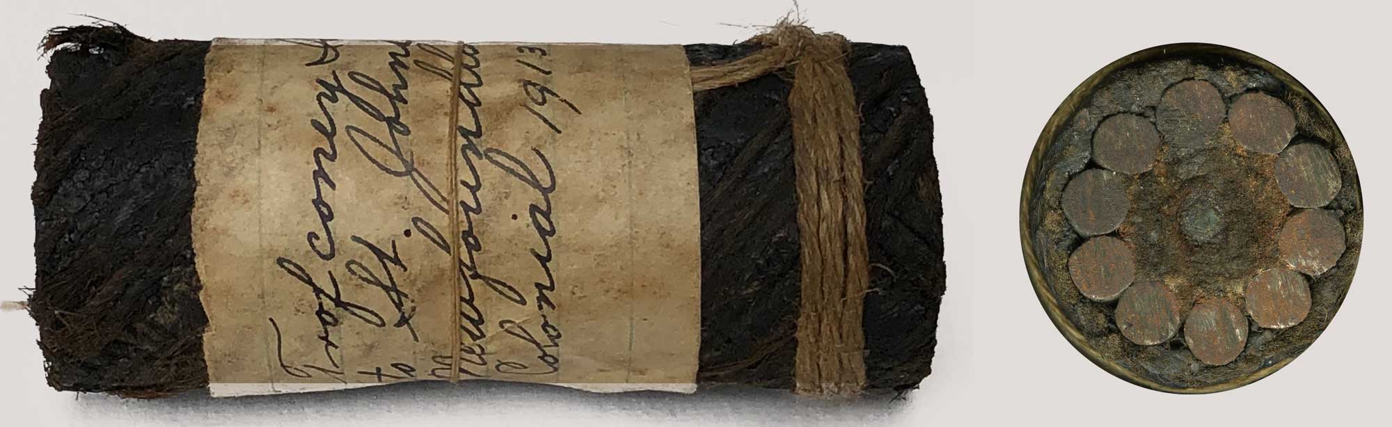
The first line of text on each entry is a verbatim transcription of the handwritten label, with errors uncorrected. For example, the Waterville label, shown in full to the right, gives the date of the cable as 1903 (actually 1905) and the ship’s name as Colonial (actually Colonia).

The photographs below of the core sections and cables are to scale, and under each image are details of the number and type of conductors, the overall diameter including the gutta percha insulation (for cores), and the length of the sample. Following this is an expanded description of the cable for which the core was used, with corrections to dates, names of ships, and other information.

While there is no provenance for this group of cores and cables, the date range and geographical locations on seven of the samples suggest that they were collected by a cable company staff member who served on one or more cableships in the North Atlantic in the latter part of the 19th century and into the beginning of the 20th. The earlier cables in the group were all made by Siemens Brothers and laid using the company’s purpose-built cableship, CS Faraday (1), and the later ones were made and laid by the Telegraph Construction & Maintenance Co (Telcon) using a variety of cableships, so it is possible that the person who collected them worked first for Siemens and then for Telcon. Both companies’ ships would have been laying new cables and performing repairs on the many existing cables on those busy routes The dates on the labels identify when each cable was first laid; repairs could have been performed many years later.

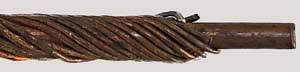
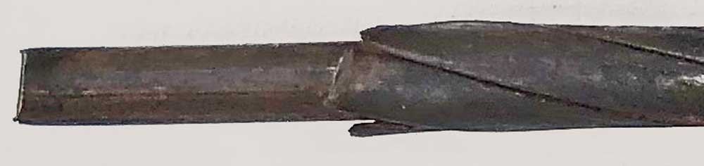
Cable Repairs: When a fault was detected in a cable, electrical measurements made from both ends could determine the location of the problem within a few miles. A cableship would then be despatched to grapple the cable on the seabed and haul it aboard for repairs, which were made by splicing in a new length of cable to replace the piece with a break or other fault. In the course of the repair the cable armouring would be stripped back to expose the core (the copper + insulation) so that the splice could be made. It would be very easy during this operation to collect as souvenirs either short sections of the core or pieces of the cable complete with armouring (as with two of the samples in this group).

Repairing a cable on board ship by replacing a defective section of cable required two splices. The splices were made in an operation called “jointing” in the cable industry. This was a critical task, as a failure in the joint would result in a loss of communication. Before the days of shipboard radio, which was not introduced until the early 20th century, the cable staff on the ship would not know if their repairs had been successful until they returned to port, so it was essential for the jointer, who had to work on the deck of the ship in all weathers, to follow very precise procedures. The techniques and tools used can be seen at the link above.

Jointing was such an important operation that the Telegraph Construction & Maintenance Co (Telcon) issued small instructional cases for each of their cableships. The case contains thirteen core sections of a typical cable of the 1880s/90s, each carefully prepared to show one of the steps in making a sound joint. Behind a glass cover in the lid of the case are illustrations and instructions for each step. The core sections in the sample case are similar in design to those from 1900 and 1905 shown below.

Conductor design: The cable samples in this group show how several different designs were used for the copper conductor over the years. The first-ever ocean cables, laid from Dover to Calais in 1850 and 1851, had a single copper wire as the conductor. This is the most efficient way to manufacture a conductor, as it uses the simplest technique for drawing copper wire down to the required diameter. Unfortunately, it is also a design with no redundancy - any stress or damage which causes the copper wire to break results in complete failure of the cable. There are no examples of this type of conductor in the group.

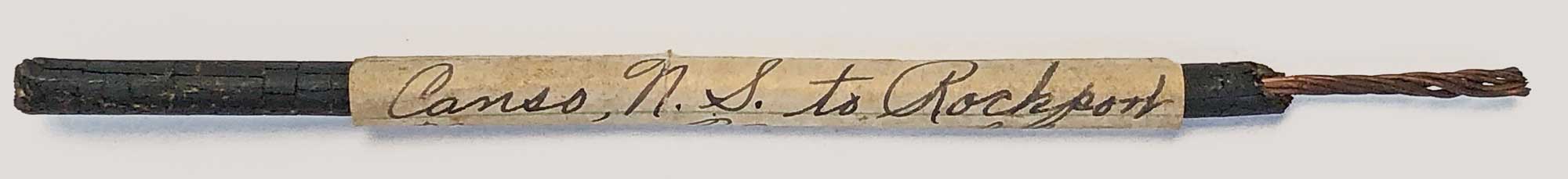
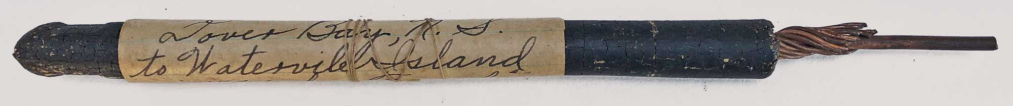
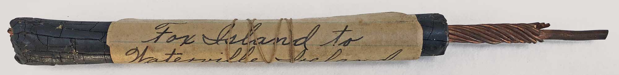
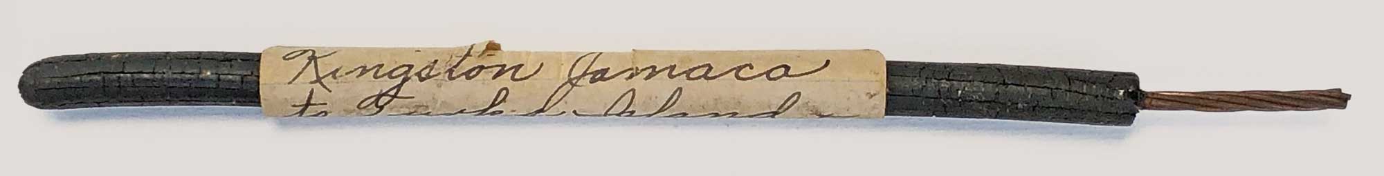
The first improvement was in 1854, when the cable across the Cabot Strait from Newfoundland to Nova Scotia used a seven-strand conductor - all wires the same gauge, with six wrapped around one. This had the advantage that if mechanical stress caused one wire to break, the circuit would remain intact. Although more complex to manufacture, this design became the standard for the next thirty years, and continued to be used for many years after that. Examples 1, 2, 5 and 9 below use this type of conductor.

As cable technology improved, and increased traffic required higher bandwidth, it was determined that for optimum signal transmission over long circuits it was desirable to pack as much copper as possible into the cross-section of the conductor. A single strand of copper was of course the easiest way to to do this, but as we have seen, this was also not the best way. The six-around-one conductor suffered from having air spaces in between the seven wires, and there was no way to improve this multi-wire strand without a new concept.

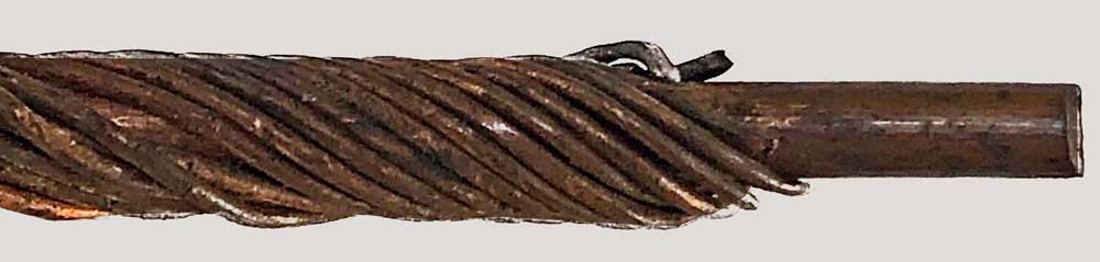
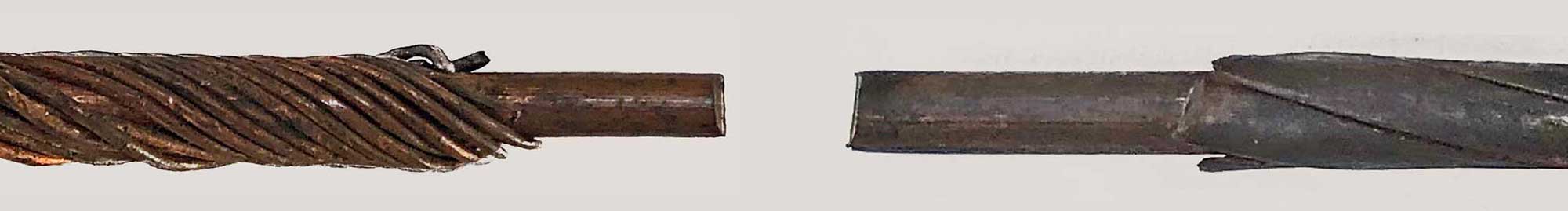
By the mid-1870s, Siemens Brothers had a solution to this problem with a new designs for their long cables, which at that time were mostly the high-traffic circuits across the Atlantic. in 1875 Siemens first used a conductor with a large centre wire, similar to that on the old single-strand conductors, but with eight (later eleven or more) smaller wires spiral-wrapped around it. These provided the essential redundancy for the conductor, and the smaller diameter greatly reduced the air gaps, producing an efficient conductor. This design can be seen in examples 3 and 4, and a magnified view of the conductor in example 3, the 1884 Ireland to Nova Scotia cable made by Siemens for the Commercial Cable Company, is shown below left.

Telcon Conductor - 4 tapes around 1 wire
German Atlantic Cable of 1900

Siemens Conductor - 11 around 1
1884 Ireland to Nova Scotia Cable

Magnified view of the two conductors side by side
This view shows that the two different designs
have almost exactly the same amount of copper

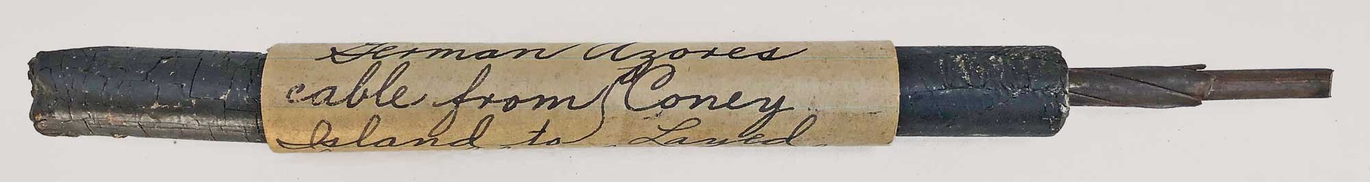
Telcon followed with similar approach, but spiral-wrapped four or six flat copper tapes around the large central wire rather than multiple small round wires. This of course resulted in no air gap at all, but the tapes would have been more expensive to make than round wires and the assembly of the conductor would have required new machinery. Examples 6 and 7 show this technique. The conductor of example 6, the German Atlantic cable of 1900, was made to Telcon’s design by the German firm of Felton & Guilleaume, and a magnified view of it is shown above right.

Both manufacturers continued to use the standard six-around-one conductor when the highest efficiency was not needed.

Gutta percha remained the standard insulation for subsea cables until the 1950s, when it was replaced by polyethylene, which could be manufactured to a consistent standard and did not require cutting down millions of trees every year. The 1950s also saw new cable designs, although the first telephone cable across the Atlantic, TAT-1 in 1956, still used the flat copper tape style of conductor, and it was not until the end of the decade that coaxial conductors became the new standard.

Details of the Core Sections and Cables
Where manufacturing records are available, the details are given in the description

1: 1875?

“The U.S. direct laid 1878 Valentia Island to Tor Bay N.S. by Cable Ship Faraday”

Complete cable sample and cross-section: 7-strand (6 around 1) conductor, 10 widely-spaced armour wires.

The cable identification on this label has several problems:
1. There were no Atlantic cables laid in 1878, and all the Atlantic cables from Valentia Island landed at Heart’s Content, Newfoundland. No Valentia cable was ever laid to Nova Scotia..
2. In 1875 (not 1878) Siemens Brothers laid a cable from Ireland to Tor Bay, Nova Scotia, for the Direct United States Cable Company using CS Faraday (1). However, the Irish end of this cable was at Ballinskelligs in County Kerry, not Valentia.
3. A diagram of the cross sections of the various types of cable used on the 1875 project may be seen at the link above. One of the examples there has the widely-spaced 10-wire armouring, but all the cables have an 8 around 1 conductor, first used by Siemens on this cable, while the sample here is the older 6 around 1 layout.

The 1865 and 1866 Atlantic cables were the first to use the somewhat unusual 10-wire armouring, and they also had 6 around 1 conductors, so it is possible that the example here is actually a section of one of those cables. All the Atlantic cables from Ireland to Newfoundland and Nova Scotia were laid on very similar routes, so a recovered section could have easily been misidentified.

2: 1884

“Canso, N.S. to Rockport Mass. Very old”

Core section: 7-strand (6 around 1) conductor, insulated with gutta percha to a diameter of 3/16". Section length 140mm.

Made and laid by Siemens Brothers in 1884 for the Commercial Cable Company using CS Faraday (1). This linked the company’s Atlantic cables at Nova Scotia to the US mainland at Rockport, Massachusetts.
Unusually, while the conductors of the main cables across the Atlantic were 11 around 1 (see below), this onbound cable from Nova Scotia to Rockport (and presumably also those to Duxbury MA and Far Rockaway NY) was 6 around 1 in a cable of only 0.5" diameter.

3: 1884

“Dover Bay, N.S. to Waterville Island in 1884 by Faraday” [Island should be Ireland]

Core section: 11 around 1 conductor, insulated with gutta percha to a diameter of 3/8". Section length 170mm.

Made and laid by Siemens Brothers in 1884 for the Commercial Cable Company using CS Faraday (1).
Dover Bay was a landing point serving the CCC’s Hazel Hill cable station near Canso, Nova Scotia.  

4: 1894

“Fox Island to Waterville, Ireland by cable ship Farada 1894.”

Core section: 11 around 1 conductor, insulated with gutta percha to a diameter of 7/16". Section length 150mm.

Made and laid by Siemens Brothers in 1894 for the Commercial Cable Company using CS Faraday (1).
Fox Island was a landing point serving the CCC’s Hazel Hill cable station in Nova Scotia.

5: 1898

“Kingston Jamaca to Turks Island & Bermuda cable ship Scotia 1898.”

Core section: 7-strand (6 around 1) conductor, insulated with gutta percha to a diameter of 1/4". Section length 163mm.

Made and laid by Telcon in 1898 using CS Scotia on the route Jamaica - Turks Island - Bermuda for the Direct West India Telegraph Co.
The Gutta Percha Company “Insulated Core” manufacturing records for December 1897 show this core as having 7/.032 wires and 3 coats of gutta percha insulation to a diameter 0.266". Total length was 1354 nautical miles, and the route was recorded as “Bermuda - Turks I. Jamaica”.

6: 1900

“Cable from Coney Island to German Azores Layed by cable ship Angler 1904.”

Core section: 4 tapes around 1 conductor, insulated with gutta percha to a diameter of 7/16". Section length 165mm.

Made and laid by Telcon in 1900 for the German Atlantic Telegraph Company using CS Anglia and CS Britannia (2).
All the types of cable used on this route can be seen at the link above, and the sample matches the core of the Azores to Coney Island cable shown there.
The conductor and armouring wires for this project were supplied by the German company Felton & Guilleaume. The Gutta Percha Company records confirm that they provided the insulation, and Telcon would then have taken the finished core and made the various types of armoured cable ready to lay. The main run from Fayal to New York was 2437.85 nautical miles, and the conductor had one .149" diameter centre wire wrapped with four tapes .124" x .017", insulated with gutta percha to a diameter of .448", almost exactly the measured 7/16" of the sample.

7: 1905

“Waterville Ireland to Fox Island 1903 by cable ship Colonial.”

Core section: 6 tapes around 1 conductor, insulated with gutta percha to a diameter of 7/16". Section length 170mm.

Rather than 1903, this cable was made and laid by Telcon in 1905 for the Commercial Cable Company using CS Colonia for the Canadian shore end.
Colonia ran aground off Fox Island and the cable was transferred to CS Mackay Bennett while Colonia sailed to Halifax for repairs. The cable route was Nova Scotia - Waterville, Ireland - Weston-super-Mare, England.
The Gutta Percha Company records show that in July 1905 they made 2330.52 nautical miles of core for this route. The conductor had one .153" diameter centre wire wrapped with six tapes .055" by .012", and was insulated with gutta percha to an overall diameter of .447", almost exactly the measured 7/16" of the sample.

8: 1906

“Havana Cuba to Coney Island 1906 cable ship Silvertown.”

Core section: 14 around 1 conductor, insulated with gutta percha to a diameter of 3/8". Section length 135mm.

It seems likely that this core section is misidentified, as the only recorded Havana to Coney Island cable was made and laid in 1907 for the Commercial Cable Company of Cuba by the India Rubber, Gutta Percha and Telegraph Works Company (IRGP) using CS Silvertown. From IRGP records, the conductor for that cable was 6 around 1 rather than 14 around 1.
The actual origin of this sample remains unknown at the moment, although the design of the conductor suggests that it may have been made by Siemens Brothers.

9: 1909 or 1912?

“Trof coney Island to St. Johns Newfoundland by Colonial 1913”

Complete cable sample and cross-section: 7-strand (6 around 1) conductor, 10 armouring wires.

The first word on the label, “Trof” is possibly an abbreviation for “Transfer of,” as some of the Newfoundland landing points of cables from New York were moved at various times.
In 1909 Telcon laid NY-1 St John’s to NY for CCC using CS Colonia. Cable type matches St John’s shore end.
In 1912 CS Colonia laid NY-2 on same route. Cable type not known.
Colonia did no work in Newfoundland after 1912, unless there was an unrecorded diversion at St John’s.

Last revised 30 October, 2022

Return to Atlantic Cable main page

Search all pages on the Atlantic Cable site

Research Material Needed

The Atlantic Cable website is non-commercial, and its mission is to make available on line as much information as possible.

You can help - if you have cable material, old or new, please contact me. Cable samples, instruments, documents, brochures, souvenir books, photographs, family stories, all are valuable to researchers and historians.

If you have any cable-related items that you could photograph, copy, scan, loan, or sell, please email me: [email protected]

—Bill Burns, publisher and webmaster, Atlantic-Cable.com