History of the Atlantic Cable & Undersea Communications
from the first submarine cable of 1850 to the worldwide fiber optic network
CS
Faraday (1)
by Bill Glover
CS FARADAY (1)
Official Number 68535
Built 1874 by C. Mitchell & Company
Ltd., Newcastle on Tyne, and retired from cable service in 1923.
Length 360.38 ft. Breadth 52.25 ft. Depth
39.6 ft. Gross tonnage 5052
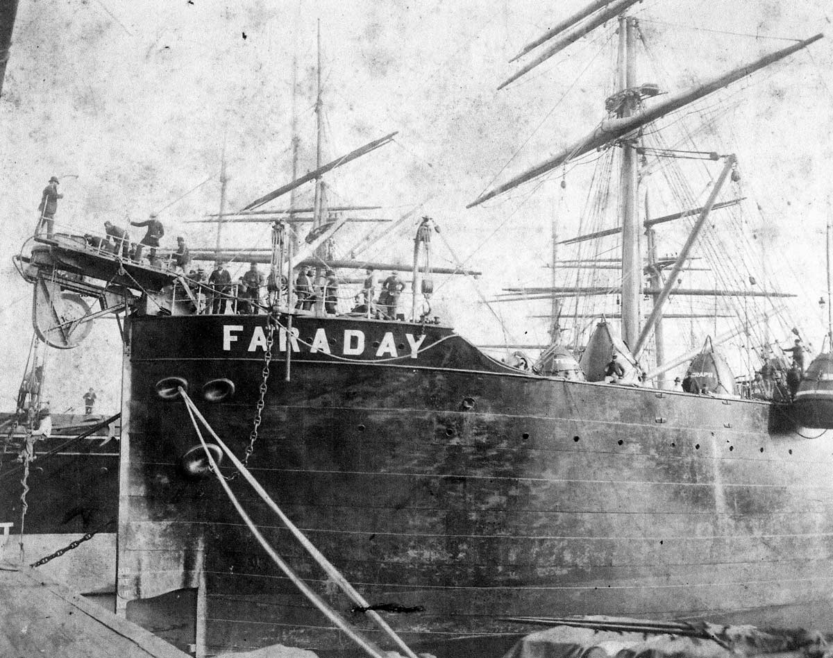
The Faraday was purpose-built for Siemens Brothers, incorporating
many of William Siemens' ideas, as he had found chartered vessels totally
unsuitable for cable laying. Two of these ideas were twin screws and a
bow rudder; another was the swivelling bow and stern sheaves which prevented
the cable from riding up the side of the sheave when ship and cable were
not in a straight line. The two funnels were placed side by side and the
bow and stern were of similar design, giving the vessel a unique appearance.
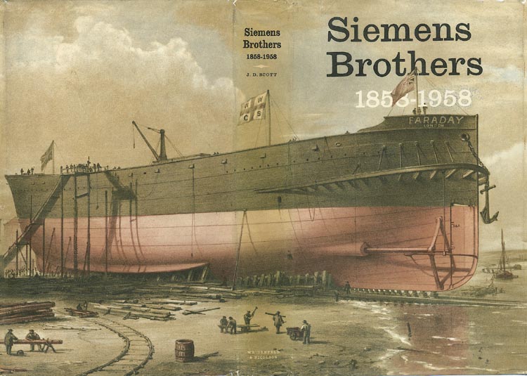
Faraday was launched at the shipyard of C. Mitchell & Company on February 17th 1874, and the event was recorded in a book written and published in 1876 by T. Fordyce of Newcastle, comprehensively titled: Local Records: or, Historical Register of Remarkable Events which have Occurred in Northumberland and Durham, Newcastle-Upon-Tyne, and Berwick-Upon-Tweed, with Biographical Sketches of Deceased Persons of Talent, Eccentricity, and Longevity.
February 17.—A new cable ship called the Faraday, a vessel of great strength and ponderous outline, was launched from Messrs. C. Mitchell and Co 's yard, Walker, in the presence of a large concourse of spectators. The occasion seemed to be one of no inconsiderable interest. Lady and gentlemen visitors were present from all parts of the district. Every arrangement had been made, under the direction of the firm, for their comfort. The raised garden in front of the manager's residence—a spot commanding a full length view of the ship—was kindly thrown open for the occasion. Gangways were also erected in convenient positions, so that the whole of the visitors had an opportunity of witnessing the launch to advantage.
Half-past three o'clock was the time fixed, and shortly after that hour the signal was given. Imperceptibly almost the vessel began to slip from the ways, and as her bow left the gangway occupied by Mrs. Siemens, of London, and a party of friends, she was named the “Faraday” by that lady, who completed the ceremony by sacrificing the customary bottle of wine. The giant structure slid gently down the incline, and dipped easily into the water amidst the cheers of the sightseers.
By means of an immense cable chain attached to anchors firmly embedded in the ground, she was brought up in midchannel, and was taken in hand by a number of tugs and towed up the river. The launch was of the most successful character, everything passing off without a hitch. The vessel was built to the order of Messrs. Siemens Brothers, London, for the purpose of laying Atlantic cables
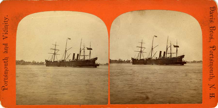
Stereoview of Faraday made by
Davis Bros., Portsmouth,
New Hampshire, part of the series "Portsmouth and Vicinity".
The view would have been made in 1874, when Faraday
was on her maiden cable laying voyage between
Rye Beach, New Hampshire, and Tor Bay, Nova Scotia
for the Direct United
States Cable Company
In almost 50 years of cable work Faraday
laid a total of 50,000 nm of cable. The ship was retired in 1923 and sold in 1924 for scrap, but the 1" thick
plates defeated the breakers and so Faraday became a coal hulk, named
Analcoal, at Algiers for the Anglo-Algiers Coaling Company. 1931
saw the hulk moved to Gibraltar, still storing coal. In 1941 the vessel
became a Naval store ship at Sierra Leone. Towed back to England in 1950,
she ended her days at a South Wales breaker's yard.
CS Faraday (1) loading cable, date and place unknown (silent film)
Includes scenes of cable being made at the factory
CABLE WORK
1874
Rye Beach, New Hampshire, USA - Tor
Bay, Nova Scotia - Ballinskelligs, Ireland
Colon, Panama - Cartagena, Colombia
Santa Elena - Chorillos
Cuba - Puerto Rico
1922
UK - Netherlands 1
FIRST WORLD WAR SERVICE
As can be seen from the list above, CS Faraday did little actual cable laying during WWI, although a new cable from England to Russia was laid for the British Post Office in the summer of 1917. This part of Russia was a major destination for Arctic convoys during WWII, and was also of strategic importance in WWI. In the 1922 book “Under the Black Ensign”
by Captain R.S. Gwatkin-Williams, the author describes the arrival of CS Faraday at Yukanskie in Russia in the summer of 1917:
During the course of the summer the British cableship Faraday arrived. She had run a submarine cable direct from England to the Kola Inlet, and thence to Arkhangel, making a loop in it so as to include Yukanskie. Delay there was whilst the Russians built a hut to accommodate the end of the cable; and further delay before operators could be found capable of working it. But before the end of the season this direct cable route was actually in operation, and as it did not run through neutral countries, nor through other parts of Russia, we hoped that for the future messages would not be tapped en route or distorted.
The Faraday herself is a wonderful old ship, even then more than forty years old, and her officers and crew seemed all to form part of one happy family. In spite of her immense size, tending to increase her vulnerability, her state of immobile helplessness, and the fact that she was continually being employed in submarine-infested waters, she passed unscathed through all the perils of war, rock and tempest. It was a year later that I saw her for the last time, in mid-Atlantic and a thousand miles from anywhere, hard at her perilous work of repairing some damaged submarine cable. How it was that the U-boats overlooked her I cannot imagine.
Despite laying few new cables the ship was not idle, and would have been engaged in cable repair and maintenance work in the North Atlantic during much of the war.
Records from the Naval History website, which has transcribed many Royal Navy log books from the wartime period, show an encounter with Faraday recorded by a ship of the British Navy. On 1 August 1918 HMS Virginian, sailing from Avonmouth to New York, “passed SS Faraday cable ship” at an unstated location (but on the following day the Virginian “sighted Cape Race”, so the rendezvous with Faraday must have been close to this point).
At the end of the war, on 11 November 1918, the day the armistice was signed, a grateful King George V sent a message to “THE NAVY”, addressed to Sir Eric Geddes, First Lord of the Admiralty. Later published in the book “The First World War in Verse and Prose,” the message began:
Now that the last and most formidable of our enemies has acknowledged the triumph of the Allied arms on behalf of right and justice, I wish to express my praise and thankfulness to the officers, men, and women of the Royal Navy and Marines, with their comrades of the Fleet auxiliaries and mercantile marine, who for more than four years have kept open the sea, protected our shores, and given us safety.
As the British fleet was dispersed around the world, the King's message would have been transmitted to all ships by any means possible. The New York Times, in its issue of 18 November 1918, reported on the arrival at New York of the SS Megantic, used during the war as a troopship, and included this note on the reception of the message by wireless:
When the news of the signing of the armistice was received by wireless late last Monday night Captain F. E. Beadnell ordered all the deck lights to be turned on for the first time since early in 1915, when the German submarines became active. All on board were roused at 7 o'clock Tuesday morning by the continuous blowing of the siren and at 8 o'clock the flag was hoisted at the stern, while the band played "God Save the King." At noon Captain Beadnell mustered the crew and the passengers on the forward deck and read a message received by wireless from King George to the Captains of all ships flying the Union Jack congratulating them for the part they had taken in assisting to win the war.
It seems likely that CS Faraday also received the message by wireless. Site visitor Paula Sloane, whose grandfather William John Stone served on the ship during this time, has a handwritten document which he saved from the Faraday:
16.5" x 13"
Although the original document is torn, the body is an exact copy of the King's message as later published. However, even though part of the heading is missing, it is clear that instead of being addressed to the Navy, it is addressed to CS Faraday. The top of the document reads, in part:
...ing Message
...[recei]ved from
...[His Majes]ty King George
...id Western Ocean to C.S. Faraday
...9.41 pm on 11th Nov 1918
"Western Ocean" referred at the time to the region of the sea around the division of today's North and South Atlantic; the message may have been sent to Faraday from the Navy command responsible for all ships in this area.
Several of CS Faraday's officers and cable staff were awarded honours in recognition of their war service:
On 15 May 1874, the day before the ship's maiden voyage, William Siemens, principal of Siemens Brothers of London, which owned and operated the Faraday, addressed a meeting of the Royal Institution of Great Britain and described his new ship:
Royal Institution of Great Britain.
WEEKLY EVENING MEETING,
Friday, May 15, 1874.
THE EARL OF ROSSE, D.C.L. F.R.S. Vice-President, in the Chair.
C. WILLIAM SIEMENS, D.C.L. F.R.S. M.R.I.
The Steamship ‘Faraday’ and her Appliances for Cable-laying.
THE speaker in his introductory remarks observed that an electric telegraph consisted essentially of three parts, viz. the electro-motor or battery, the conductor, and the receiving instrument. He demonstrated experimentally that the conductor need not necessarily be metallic, but that water or rarefied air might be used as such within moderate limits; at the same time, for long submarine lines, insulated conductors strengthened by an outer sheathing were necessary to ensure perfect transmission and immunity from accident. The first attempts at insulation, which consisted in the use of pitch and resinous matters, failed completely, and in the years 1846 and 1847 the two gums, india-rubber and gutta-percha, were introduced, the former by Prof. Jacobi of St. Petersburg, and the latter by Dr. Werner Siemens of Berlin. This last gum soon became almost indispensable to the cable manufacturer on account of its remarkable plasticity at low temperatures and its insulating property.
The first outer sheathing used was a tube of lead drawn tightly over the insulated wire, and this again was covered with pieces of wrought-iron tubing connected by ball and socket joints; in this way the Elbe and other rivers were crossed successfully in 1848-50. This method was superseded later on by the spiral-wire sheathing, first proposed by Mr. Brett in 1851 for the Dover and Calais cable; since then, with few modifications and exceptions, this form has been universally adopted.
The speaker next enumerated the casualties to which submarine cables are liable, and the precautions employed to obviate them. He showed specimens destroyed by rust and the ravages of a species of teredo. On the Indo-European Cable line a curious case of fracture occurred; a whale, becoming entangled in a portion of cable overhanging a ledge of rock, broke it, and in striving to get free had so wound one end round its flukes that escape became hopeless, and so had fallen an easy prey to sharks, which had half devoured it when the grappling iron brought his remains to the surface. Other enemies to be dreaded are landslips, ships’ anchors, and abrading currents.
The new Atlantic cable consists, for the deep-sea portion, of copper conductors, gutta-percha insulators, and a sheathing of steel wires covered with hemp; the shallow-water part consists of similar conductors and insulators sheathed with hemp, which in turn is covered with iron wire.
In paying out, no catenary is formed, as might be supposed, but the cable passes in a straight line from the ship to the sea-bottom—-a proposition which the speaker demonstrated experimentally by means of a long trough with glass sides filled with water. The retaining force applied by the brake wheel should be equal to the weight of a piece of cable hanging vertically downwards to the bottom of the sea. In picking up, a catenary is formed, but a vertical position is the best, because it produces the least resistance.
From the peculiar nature of the service for which a telegraph-ship is required, it is evident that she must possess properties somewhat different from those of ordinary ocean-going steamers; thus speed is not so important as great manoeuvring powers, which will enable her to turn easily in a small space, or by which she may be maintained in a given position for a considerable time. In the ship about to be described an attempt had been made to meet these requirements.
The ‘Faraday’, of 5000 tons register, was built at Newcastle by the eminent firm of Messrs. Mitchell and Co. She is 360 feet long, 52 feet beam, and 36 feet depth of hold; there are three large watertight cable tanks having a capacity of 110,000 cubic feet; these are each 27 feet deep; two are 45 feet in diameter, and one is 37 feet; they can take in 1700 miles of cable 1¼ inch in diameter. After the cable is coiled in, the tanks are filled up with water to keep it cool; for the speaker had found, when conducting experiments on the Malta and Alexandria cable with his electrical resistance thermometer, that heat was spontaneously generated in the cable itself, whereby its insulation was seriously endangered.
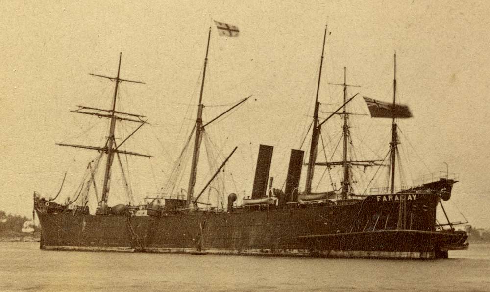
Detail of 1874 stereoview.
The flag flying from the middle mast is the Siemens Brothers company
flag,
a St. George's cross (red on a white ground) bearing the brothers'
initials.
The ‘Faraday’ has stem and stern alike, and is fitted with a rudder at each end; both are worked by steam-steering apparatus placed amidships, and are capable of being rigidly fixed when required. She is propelled by a pair of cast-steel screw propellers 12 feet in diameter, driven by a pair of compound engines constructed with a view to great economy of fuel. The two screws converge somewhat, and the effect of this arrangement is to enable the vessel to turn in her own length when the engines are worked in opposite directions. On the voyage from Newcastle to London a cask was thrown overboard, and from this as a centre the ship turned in her own length in 8 minutes 20 seconds, touching the cask three times during the operation. This manoeuvring power is of great importance in such a case as repairing a fault in the cable, as it enables the engineer to keep her head in position, and, in short, to place her just where necessary, in defiance of side winds or currents.
The testing-room of the electrician in charge is amidships, and so placed as to command the two larger tanks, while the ship’s speed can be at all times noted on the index of a Berthon hydrostatic log.
The deck is fitted with machinery to be used in laying operations, which will be best described by tracing the path of the cable from the tanks to the sea. Let us begin with the bow compartment: the cable, which lies coiled round one of Newall’s cones, begins to be unwound, passes up through an eye carried on a beam placed across the hatch, next over a large pulley fitted with guides, and by a second pulley is gently made to follow a straight wooden trough fitted with friction rollers, which carries it aft to near the funnels; here it passes through the “jockey,” which is a device for regulating the strain, consisting of a wheel riding on the cable, which can be adjusted by a lever, and a drum fitted with a brake. Thence it passes on to a “compound paying-out and picking-up machine,” which consists of a large drum provided with a friction brake, and round it the cable passes three times; it is also furnished with a steam-engine, which by means of a clutch can be geared on to the drum when required. Now, in paying out, the cable causes the drum to revolve as it runs over it, and the brakes regulate the speed as the vessel moves onward; but should a fault or other accident render it necessary to recover a portion, the drum is stopped and geared on to the engine, the ship’s engines are reversed, the stern rudder fixed; and so what was formerly the bow is now the stern, while the little engine hauls in the cable over the same drum which before was used to pay it out; thus it is coiled back into the same tank whence it started. By this means the necessity of passing the cable astern before proceeding to haul it in is avoided. It was during this operation that an accident befell the Atlantic cable in 1865, causing its loss for the time.
The next apparatus is a dynamometer, consisting of three pulleys, one fixed, and the centre one, which rests on the cable, movable in a vertical plane; by this the strain is registered and adjusted. After passing this the cable runs into the sea over a pulley carried on girders and constructed so as to swing freely on an axis parallel to the length of the ship, so that, should the vessel make lee-way, the pulley will follow the direction of the cable, and thus friction and sharp bends are avoided. The bows are also fitted with a similar pulley, compound machine, and dynamometer. We see that by these devices the cable is kept perfectly under control, and should a fault be discovered a simple process of reversal of ship and machinery brings home the faulty portion.
Another great point is to keep the vessel trimmed and steady. For the former requirement nine separate water-tight compartments, including the cone in each tank, which also is hollow, are provided, so that water may be admitted as the tanks are emptied of cable, and thus the ship is kept trimmed. To ensure steadiness and avoid the rolling to which telegraph ships are subject, two bilge keels are set on at an angle of 45 deg; this was done at the suggestion of Mr. Wm. Froude, whom, said the speaker, “I have to thank for valuable advice and assistance on several new points connected with the ‘Faraday.’”
A steam-launch is carried on deck, whence she can be lowered into the water with steam up, ready to land shore ends and perform other useful operations.
Another class of work for which the vessel is fitted is “grappling” for lost or faulty cable. In shallow seas this is a very simple operation, but in deep water it is rather a delicate matter, and requires the co-operation of two or even three vessels, so as to lift the cable without forming an acute angle, and thus to lessen the chance of fracture. A special rope, made of steel wire and hemp and of great strength, is provided for this work. Some specimens shown could bear strains up to 16 tons.
In conclusion, the speaker adverted to the late Professor Faraday, noticing the great services he had rendered to electrical science, his singleness of purpose, and the invariable kindness with which he had encouraged younger labourers in the same field. The friendly encouragement which he himself had experienced from him would ever remain a most pleasing remembrance. He had seized with delight on the present opportunity to pay a tribute to the honoured name of Faraday, and was happy to be able to do this with the full consent of the revered lady who had stood by the philosopher’s side for forty years, while labouring under this very roof for the advancement of knowledge. The name of the vessel and her mission in the service of Science would combine, he thought, to create an interest in her favour in the minds of the members of the Royal Institution, and he hoped that on the morrow she would put to sea accompanied by the earnest wish, “God speed the ‘Faraday.’”
[C.W.S.]
[Excerpt from The Journal of the Royal Institution of Great Britain, Vol VII, 1874, pp. 310-313. Text courtesy of Special Collections, Smithsonian Institution Libraries.]
Cableship crew had to send and receive their mail whenever and wherever they could. This 1913 postcard was sent from Colombo, Ceylon by a Faraday crew member (Charlie) while on route to the Dutch East Indies:
Perhaps the last photograph of CS Faraday (1) in service, circa early 1920s, loading cable at the Siemens Brothers Woolwich factory:
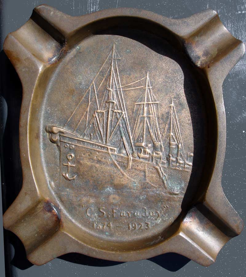
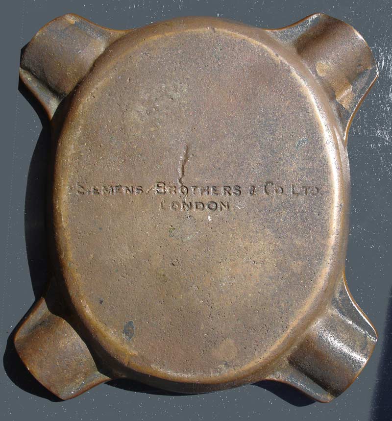
Chris Craven sends the photos below of an ashtray commemorating CS Faraday. His father, cable jointer George Craven, worked on cableships for many years and told Chris that this was made from the propellor of the Faraday after the ship was scrapped.
Photographs and details of a model of the Faraday, made by Mr Daniel Aldous, an electrical mechanic who served on the ship in the late 1800s, may be viewed at the website of the Museum of Applied Arts and Sciences, Sydney, Australia.
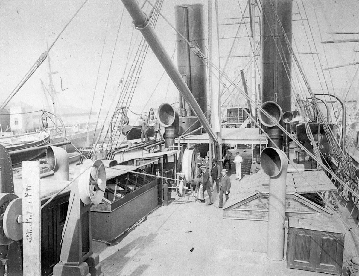
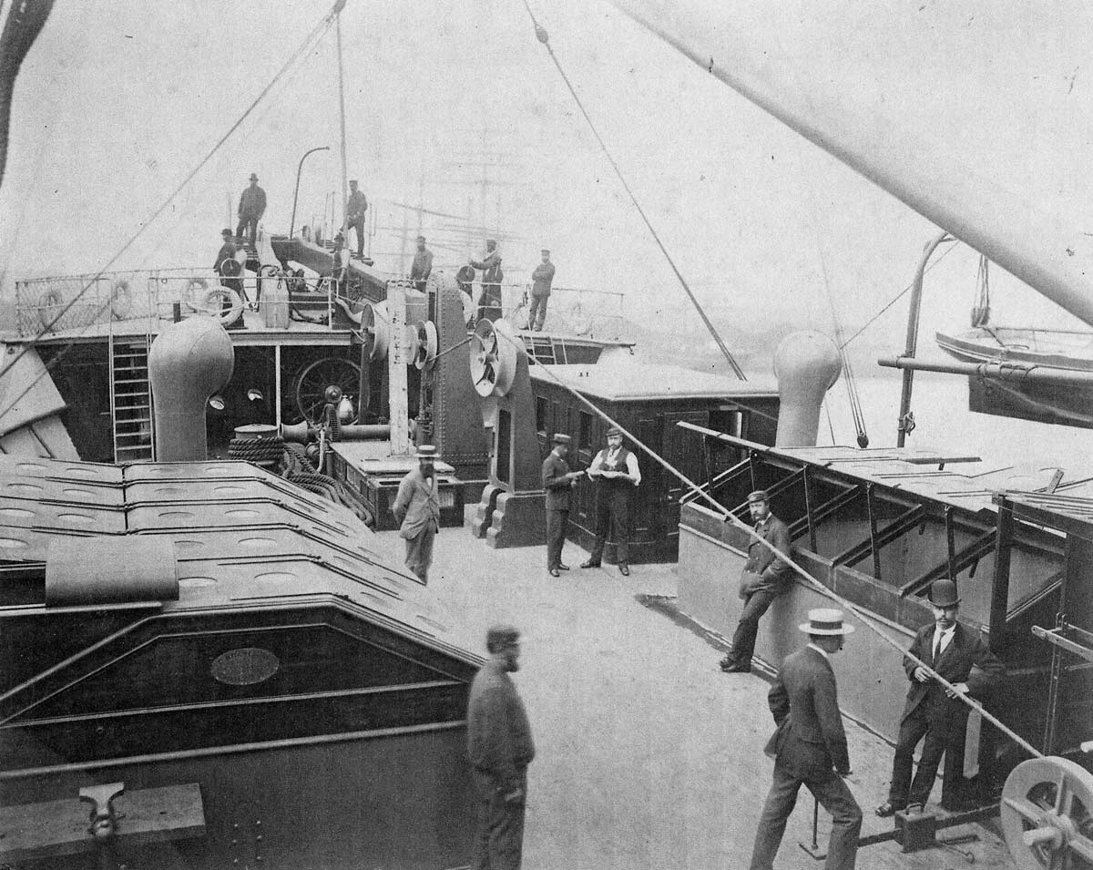
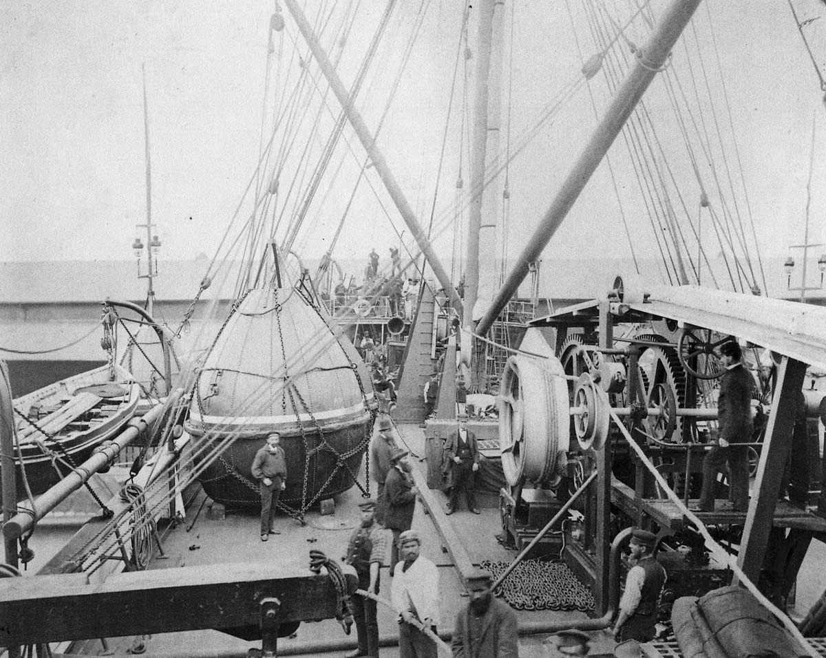
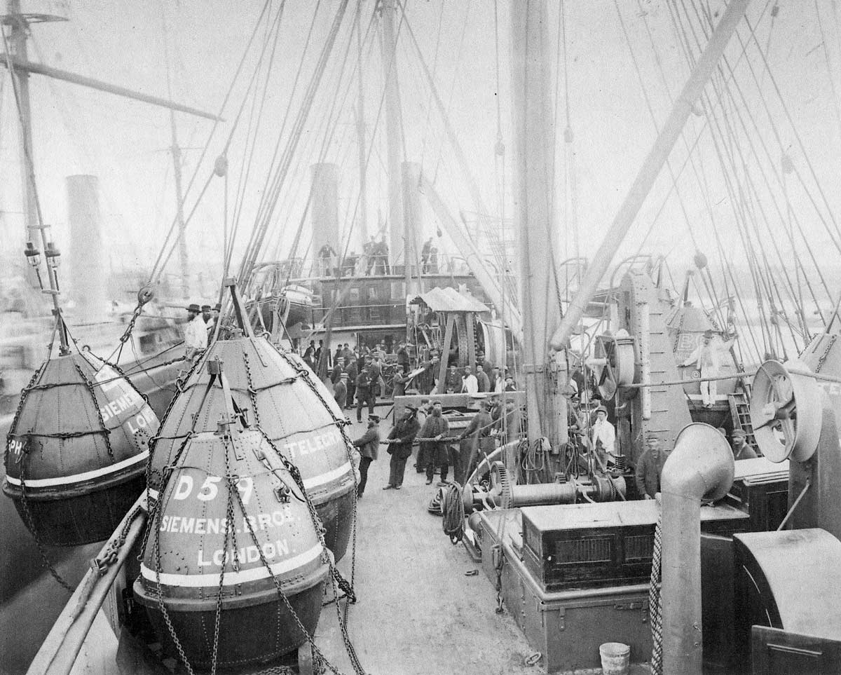
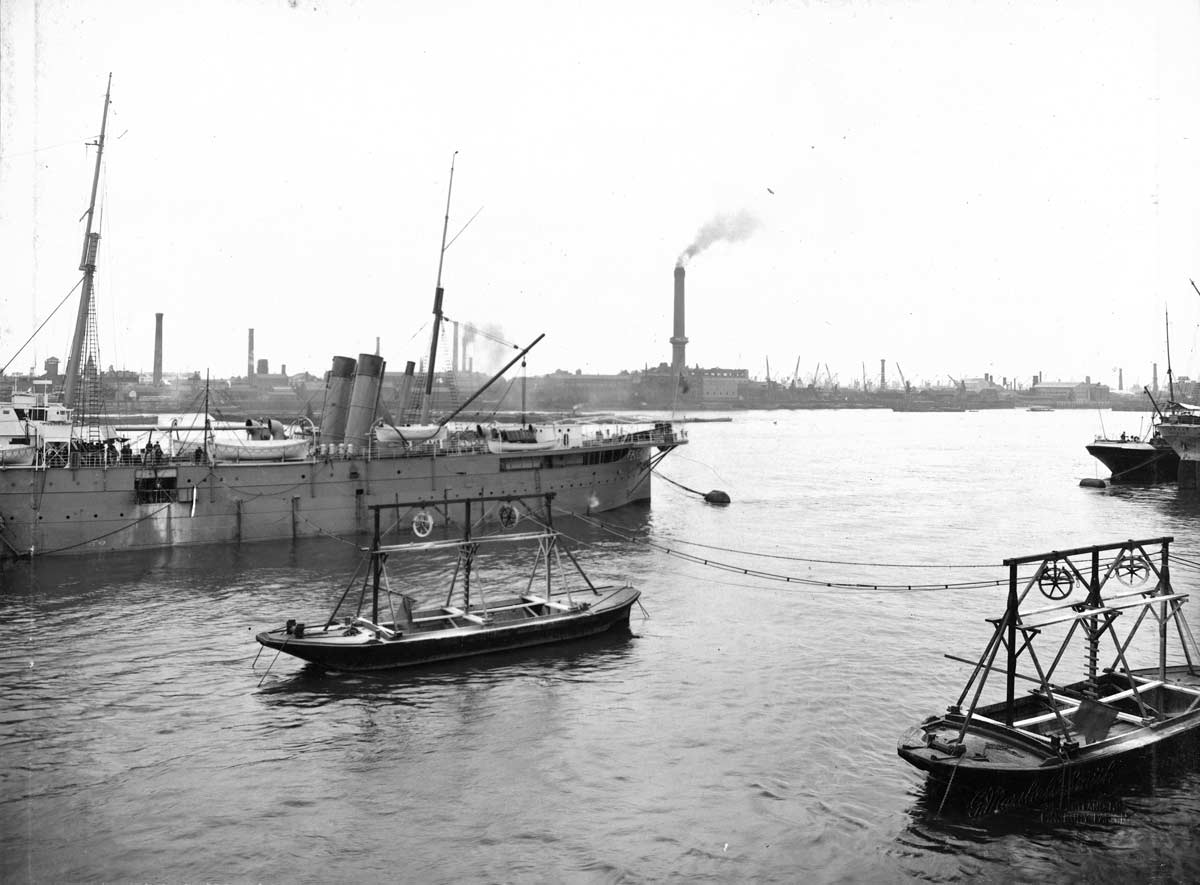
Thanks to site visitor Hans Henke for providing the following copies of his Faraday photographs, which include seldom-seen views of the machinery and equipment. A caption to one of the photos at another source has this description, and gives the date as circa 1896:
LINKING THE CONTINENTS: A CABLE SHIP AT WORK. We here see a deep-sea cable being paid out from Messrs. Siemens’ telegraph ship, a vessel fitly named The Faraday, after one of Britain’s greatest men of science. Despite the perfection of the paying-out machinery, and the strength and flexibility of the modern cable, breakages still occasionally occur, and then the work of grappling on the ocean bed has to be undertaken. Sometimes a defect in a unbroken cable has to be discovered and repaired, but the ingenuity of the electrician can now discover the precise spot where the flaw exists. The resistance of the copper wire in the cable to its point of contact with the sea is measured against the known resistance of a series of coils. This is done so accurately that the injury may be located at a point a thousand miles away from the shore, and the great ship may safely make her way to a fixed spot in the centre of the ocean, and there grapple for the cable with the certainty that a thousand fathoms under her keel the little fracture will be found.
The Atlantic Cable website is non-commercial,
and its mission is to make available on line
as much information as possible.
You can help - if you have cable material,
old or new, please contact me. Cable samples, instruments, documents,
brochures, souvenir books, photographs,
family stories, all are valuable to
researchers and historians.
If you have any cable-related items
that you could photograph, copy,
scan, loan,
or sell, please email me: [email protected]
—Bill Burns, publisher and webmaster: Atlantic-Cable.com


-Ceylon-PPC.jpg)
-Ashtray-BB.jpg)