History of the Atlantic Cable & Undersea Communications
from the first submarine cable of 1850 to the worldwide fiber optic network
The
Newfoundland-Azores High-Speed Duplex Cable (1928)
by J.W. Milnor and G.A. Randall
|
History of the Atlantic Cable & Undersea Communications |
|
The
Newfoundland-Azores High-Speed Duplex Cable (1928) |
|
|
The
Newfoundland-Azores High-Speed Duplex Cable
Presented at the Winter Convention of the A.I.E.E., New York, N. Y., January 26-30, 1931 Synopsis: A description is given of the cable laid by the Western Union Telegraph Company in 1928 between Newfoundland and the Azores. The plan of this cable is unique in that it consists of a combination of non-loaded and loaded cable, the latter being tapered throughout certain portions. By means of this arrangement it has been possible to secure duplex or two-way operation at a speed of 1400 letters per minute in each direction. The general methods used in obtaining the duplex balance are described and the fundamental theory of the cable is given. In September 1928 the final splice was made in a submarine telegraph cable of a new type connecting Bay Roberts, Newfoundland, and Horta, Azores. This cable adds an important link to the transatlantic cable system of the Western Union Telegraph Company. From Newfoundland it is extended to New York by land line connections, and at Horta connections are made with German and Italian cables. This cable combines the advantage of high-speed operation characteristic of the new continuously loaded cable, with the facility of duplex or two-way operation inherent in the old non-loaded type of cable. Tests have shown that a signaling speed of 1400 letters per minute cable code (42 cycles per second) simultaneously in both directions is now practicable, and the indications are that the ultimate duplex speed may be somewhat higher. If operated simplex, i.e., in one direction only, the speed is somewhat over 2500 letters per minute. The duplex speed is several times as high as any long cable has previously been duplexed, and provides the greatest message capacity of any existing trans-ocean cable. Prior to 1890, Heaviside had shown the important relation which exists between the inductance of a cable and its operating speed. However, it was not until recently that this knowledge could be applied to long telegraph cables, as a result of the development by the Bell Telephone Laboratories of a new magnetic alloy, permalloy, and of means for applying it to submarine cables. [note 1] The first cable of this type was laid by the Western Union Telegraph Company between New York and Azores Islands in 1924. The results obtained on that cable fully justified expectations and since then a total of eight other continuously loaded cables has been laid by various companies in the Atlantic and Pacific Oceans.
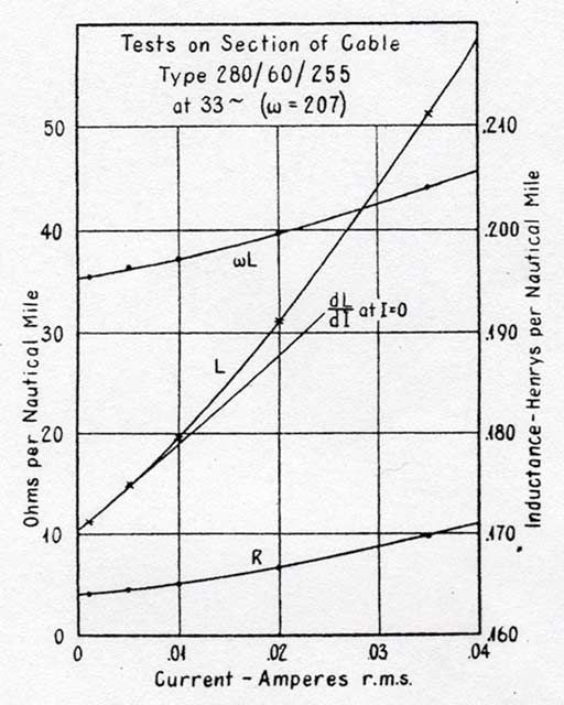
It has long been customary for the relatively slow speed non-loaded submarine cables to be operated simultaneously in each direction. [note 2] The electrical characteristics of loaded cables are such that they are much more difficult to duplex. For this reason all loaded cables laid between 1924 and 1927 were designed to be operated simplex only. Special devices were developed for quickly reversing the direction of transmission at regular intervals which may be as short as one minute. There are many situations, however, where duplex operation is decidedly advantageous, and it was inevitable that attempts should be made to develop a cable capable of high-speed duplex operation. The desired result was obtained in the cable here described through the use of a combination of loaded and non-loaded cable, the latter being adjacent to the ends. GENERAL THEORY OF DUPLEX CABLES In order to duplex a cable, it is necessary to provide at each terminal station a so-called artificial line which closely simulates the impedance of the cable as measured from its end. The highest practicable accuracy of balancing is desirable, as the cable efficiency is thereby increased. The two impedances should closely match throughout a range of frequencies from about half the fundamental signaling frequency up to about 1.6 times that frequency; a somewhat less accurate balance is necessary at frequencies outside of that range. A loaded cable is more difficult to balance than non-loaded cable for three reasons: 1. There are irregularities in the impedance as measured at different points along a loaded cable, which are much more pronounced than if non-loaded. Difficulties in manufacture are such that variations from the mean values of inductance are appreciable and unavoidable. 2. The effect on balance of such irregularities is more prominent in a loaded cable. The reason for this is that the velocity of wave propagation is slower and therefore the reflections from different parts of the cable tend to appear distinct, while in the non-loaded cable they are relatively merged. A more accurate balance is therefore necessary with loaded cable. 3. The impedance of a loaded cable is not constant. The inductance due to the loading material, as well as the effective resistance, vary with current as indicated in Fig. 2. The signaling current, of course, continually changes in magnitude, consequently the cable impedance undergoes frequent small variations.
Each of the above difficulties is reduced in importance by loading only the central portion of the cable, the end sections being non-loaded. For the non-loaded portion, a duplex balance is obtained having about the same order of accuracy as has been customary in the past in cables which are non-loaded throughout their their length. In the part of the artificial line corresponding to the loaded portion, a duplex balance of a much lower degree of accuracy is sufficient, since it is distant from the terminals. [note 3] The correctness of the above will be made evident in the Appendix, in which a more complete exposition is given of the influence of various factors. Some of these factors may be briefly summarized as follows: The permissible attenuation from end to end of the cable as measured at the working frequencies, is determined by the degree of accuracy with which the artificial line as a whole can be adjusted to match the impedance of the cable. With higher accuracy a greater attenuation is permissible. The attenuation which is permitted from end to end of the loaded portion of the cable is determined by the accuracy with which the impedance of that portion of the cable can be matched in the corresponding portion of the artificial line. In order that the most economical design of cable may be obtained, it is necessary that special consideration be given to methods for improving the stability of the impedance of the loaded portion of the cable, as affected by changes in the inductance of loading caused by varying current. The amount of change of inductance with current may be controlled to some extent through variations in the core design and in its treatment during manufacture. By the use of sea earths of proper length at the ends to hold the level of extraneous interference to as low a value as readily practicable, the use of a lower battery voltage at the opposite end of the cable is made possible. This results in lower current strength throughout the cable, with a corresponding gain in stability. DESCRIPTION OF 1928 CABLE A theoretical study completed in January 1928, had indicated the commercial practicability of this type of duplex cable. At that time telegraph traffic on the simplex loaded cable previously laid between New York and Azores, was growing so rapidly that some increase in the facilities was urgently needed. This growth could be met only by providing a second connection all an early date, and it was considered desirable to take advantage of this new development in the cable about to be laid. Because of the nature of the new technical problems involved in the design of the cable and its balancing equipment, and the lack of time in which to make proper experimental confirmation of some of them, it was considered advisable that the cable be so constructed as to permit simplex operation, if for any reason the duplex balancing should not prove satisfactory. However, it was found that in order to provide for simplex operation at the higher speed, it was unnecessary to make any important change from the design which was found to be best for duplex working.
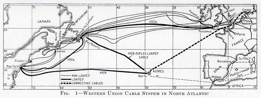
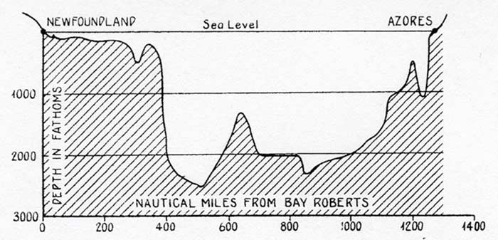
The formal order for the manufacture was placed in March. 1928, although some details of the design were not completed until much later. The cable was manufactured by the Telegraph Construction and Maintenance Company, Ltd. of London, and laid by their cable ship "Dominia," the laying being completed on September 1st of that year. The route followed by the cable is indicated in Fig. 1. A profile chart showing its depth is given in Fig. 3. Plan of Cable. The total length of the cable is 1341.2 nautical miles. The non-loaded end portions are each 160 miles in length. The remainder of the cable is loaded, two different weights of conductor and loading being used. In Table 1 are given further details of the design, together with the results of electrical tests.
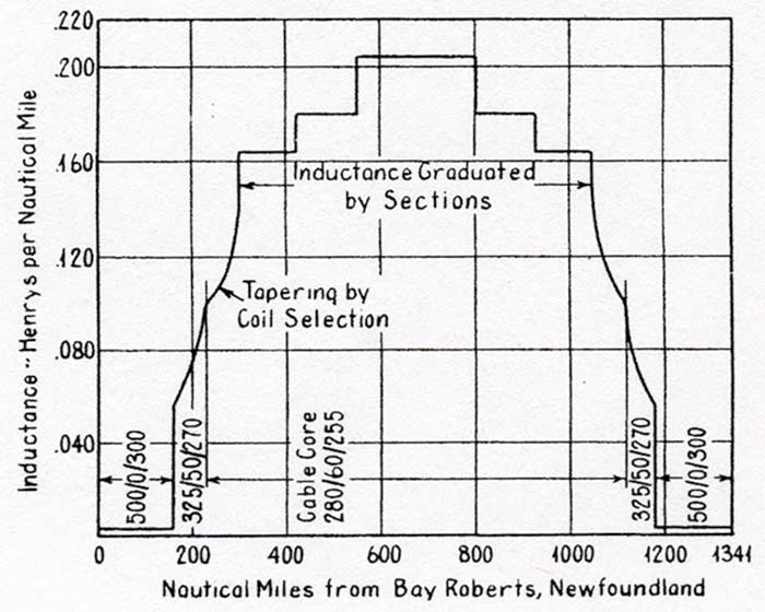
Conductor. The conductor consists of a solid copper central wire closely surrounded by five or six thin copper tapes. Loading The loading throughout the central portions is supplied by the Telegraph Construction & Maintenance Company. This material is similar in general composition and characteristics to permalloy. The wire is wound directly on the copper conductor in a close continuous wrapping. The heaviest loading wire is about 0.008 in. in diameter. It is estimated that the total length of loading wire in this cable is about 50,000 miles. An inductance range from 0.056 to 0.230 henrys per mile was obtained in different portions of the cable through controlled variations in the annealing of the loaded conductor. The average values of inductance in the various sections are indicated in Fig. 4. The permeability (corresponding to small magnetizing forces) ranges from 2000 to 6800. This maximum value materially exceeds any previously obtained in cable construction.
A special asphaltum flux was used to fill the interstices of the loaded conductor, for the purpose of equalizing pressure upon this strain-sensitive loading material. Insulation and Armoring. The conductor, either loaded or non-loaded, was covered with a conservative thickness of a gutta percha mixture for purposes of insulation, in accordance with usual cable practise. This in turn was covered with wrappings of jute and a sheath of iron or steel wires to provide tensile strength and protection against injury. The portions near shore have much heavier sheathing than the main sections, and in addition have a wrapping of brass tape applied to the core as a precaution against injury by the teredo. Sea Earths. The cable is single cored excepting near the ends. In order to reduce as far as possible the extraneous voltages picked up in shallow water, it is customary in cable practise to carry a second and sometimes a third core in the sections of cable near the ends. These additional cores are grounded at their outer ends to the cable sheath. At Bay Roberts the distances out to the end of the longer or receiving sea earth is 50.10 nautical miles. At Horta, Azores the corresponding distance is 2.39 nautical miles. The receiving sea earth connection at Bay Roberts differs from the other sea earth connection in the fact that a manganin resistance of 160 ohms is connected at sea in series with the sea earth core. This resistance assists in equalizing any extraneous voltages picked up by cable and sea earth cores between that point and the receiving apparatus. CABLE TESTS Various tests were made during manufacture and upon the laid cable in order to ascertain its performance characteristics. The results of the d.c. tests are as follows:
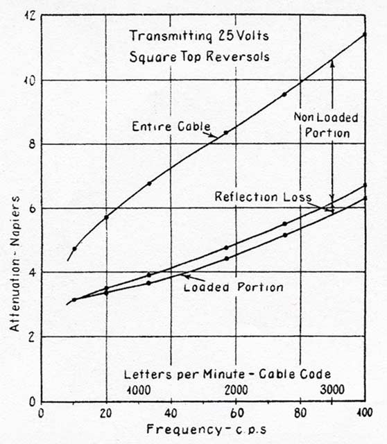
The attenuation of the cable was measured in each direction at various frequencies and with several sending voltages. The results of some of these tests are shown in Fig. 5. The curves show the attenuation of the fundamental frequency of a square-topped transmitted wave. The effect of changing the sending voltage was found to be small.
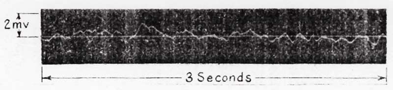
The time of propagation of signals over the cable is 0.235 seconds at 60 cycles. Based upon the measured values of time of propagation and attenuation at various frequencies, it has been estimated that during the process of laying, the strains placed on the cable caused an average loss in the inductance of about 13 per cent. In Fig. 6 is shown a record of interference obtained at Newfoundland, using the 50-mile sea earth. At Azores where the cable reaches deep water within a few miles, the interference is much less. ARTIFICIAL LINE EQUIPMENT An essential part of this cable project has been the provision at each cable station of an adequate artificial line for completing the Wheatstone Bridge arrangement which is necessary for duplex operation. This line is a network which is an electrical image of the cable, designed to match it mile for mile as accurately as is necessary for the purpose. A certain amount of work has been done by others [note 4] with a view to providing a network for general use which would contain less electrical capacity than the actual cable, and would therefore be relatively inexpensive. The resultant network has always been complicated in theory and possibly difficult to adjust. In the present work, no attempt was made to use such devices.
The present equipment is somewhat more complicated than in the case of the usual artificial line for low speed cables. For a non-loaded cable the network usually consists of units of resistance and capacity only. In addition to these two elements, the present equipment includes means for simulating the inductance of both non-loaded and loaded portions, eddy current losses in the loading, sea return losses, and dielectric losses. A compensating arrangement is introduced to prevent filter oscillations between the condenser and inductance units of the artificial line, in order to avoid the use of an excessive number of coils. The artificial line is adjustable in every portion, the size of the steps at each point of the line depending upon the accuracy of impedance matching required at that point. As originally installed, the artificial lines were set up on the basis of computed values, the initial error in matching being of the order of one per cent. Uncertainties in the exact distribution of the cable constants themselves prevented a closer initial balance. The final balances were obtained by a systematic adjustment of the various elements composing the line. As in the case of the cable itself, the change of inductance with current in the coils of the artificial line must be given consideration in their design. In theory it might be practicable to provide artificial line coils whose inductance would vary with current in the same manner that the inductance varies in the corresponding portion of cable, thus permitting the use of relatively larger inductance variation in designing the cable. Such procedure would greatly increase the complexity of the artificial line. It was therefore considered desirable to hold the current-inductance coefficients (defined in the Appendix) of both the cable and artificial line to relatively small amounts, the values for the artificial line being kept smaller than those in the cable. Because of the use of inductance coils, some other unusual precautions were necessary in this line. In the usual artificial line, the resistance elements are of wire having low temperature coefficient. This wire did not appear to be practicable in the inductance coils, and in order that the line should not be unusually susceptible to temperature changes, the copper resistance of the coils has been kept at a relatively low value. This necessitated larger coils than would otherwise have been used. Special precautions have been taken to prevent pick up of extraneous disturbances by the coils. This is accomplished by a method of mounting and wiring the coils which effectively transposes them with respect to external fields. Each artificial line occupies a space of approximately 210 cu. ft. These lines are mounted in heat-insulated cabinets. To correct for variations in the balance due to temperature changes along the cable and to a less extent in the artificial line, five adjustable resistances have been provided in the operating room. Observations over a period of more than a year indicate that these resistances need not be altered more than once daily to maintain a satisfactory balance. The method used in making the final field adjustments to the artificial lines is not new, being similar in principle to that used for many years with non-loaded cables, excepting that a high-speed recording device was used to observe the balance. During the greater part of the work a single reversal at a time was transmitted into the cable, while a record was obtained of the resulting current caused by lack of perfect balance. In the final refinements of balance different combinations of telegraphic signals were sent at various speeds. A Western Electric Signal Shaping Amplifier [note 5] is used both during balancing and for commercial operation, the amplifier being standard except for a few minor alterations and additions.
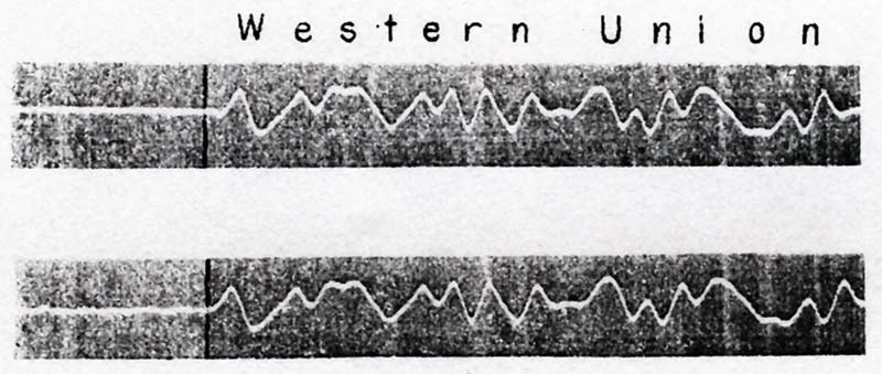
In Fig. 7 are shown records of characters received, both simplex and duplex, over the cable. The speed here is 1400 letters per minute cable code. A 12-volt battery was used for sending, and the strength of received signal with reversals at the above speed is about six millivolts. It has been estimated that the impedance of the artificial line matches that of the cable to an accuracy of roughly one part in 4000, as determined when telegraph characters are transmitted. Such characters may be considered to be made up of many frequencies sent simultaneously. When determined with a sinusoidal voltage in the frequency range between 35 and 55 cycles, the estimated accuracy is better than one part in 7000. RELATIVE MERITS OF SIMPLEX AND DUPLEX HIGH-SPEED CABLES In determining the kind of cable facilities best suited for handling telegraph traffic between two given areas, there are many factors which must be considered, and individual consideration for each project is therefore required. The relative advantages and economics of simplex and duplex cables depend to a certain extent upon the length of the circuit and the desired message capacity. Consideration must be given to the relative amounts of urgent and deferred traffic; the difference if any in the load in the two directions; and the difference in time between the terminal areas. The nature of any existing cable facilities between the terminals must be taken into account in determining the method of increasing the facilities. It is also important to consider the manner in which the traffic would be handled in the event of a failure of one or more cables. Where the load between two points is sufficient to justify only a single cable, and the difference in time between terminals is not excessive, the duplex type usually offers the most convenient method of handling it. An alternative arrangement is a simplex cable with automatic direction reversing equipment. The latter plan necessarily results in part of the traffic being somewhat delayed, a condition which in some cases is objectionable. In addition, much of the terminal equipment is idle half the time, and when working must be operated at relatively high speed. On the other hand, the duplex cable requires the somewhat complicated artificial line networks. If the terminals of the cable circuit are so located that there is a considerable time difference between them, as for example between America and Japan, the simplex cable has the advantage, since the greater part of the traffic flows in one direction at a time. Where the amount of traffic is enough to justify two or more cables, there are various possible solutions. The equivalent of a duplex circuit can, of course, be obtained through the use of two simplex cables worked in opposite directions. Ordinarily, however, the rate of traffic growth is not sufficient to justify laying two cables at the same time or within short periods. In some cases, a combination of simplex and duplex cables may be found to be the best ultimate solution when all factors are taken into account. It appears probable that neither the simplex nor the duplex cable has as yet reached its limit of economical development, hence it is hardly practicable at this time to give a final answer to the above questions. ACKNOWLEDGMENTS The fact that the application of non-loaded ends to a loaded cable would facilitate duplex working was discovered independently by Mr. J.J. Gilbert of the Bell Telephone Laboratories, and by the first named of the authors. The cable under discussion and the duplexing equipment were developed, designed and balanced by engineers of the Western Union Telegraph Company. Important contributions were made by Messrs. C.H. Cramer and W.D. Cannon. Most of the field adjustments of artificial lines were in charge of Mr. E.L. Newell. The route and the sheathing structure for the cable were worked out by Mr. V.H. Rowland. Notes 1. "Permalloy,
An Alloy of Remarkable Magnetic Properties," by H.D. Arnold and G.W.
Elmen, Jour. Franklin Inst., v. 195, 1923, p. 621. 2. Duplex operation was first introduced in 1871. 3. It should not be inferred from these statements that it would be impossible to duplex an all-loaded cable. If by proper design the attenuation from end to end were held to a reasonably low value, and other factors are correct, a balance should be practicable. The combination of loaded and non-loaded cable was used in the present case in order to obtain the desired results at a minimum expense. 4. One of these methods is described by H. Salinger and H. Stahl, "The Simulation of Long Submarine Cables," Electrische Nachrichten Technik, August, 1926. 5. "Applications of Vacuum Tube Amplifiers to Submarine Telegraph Cables," by Austen M. Curtis, Bell System Technical Jour., July, 1927. Editor's notes: The Appendix, referred to in the text, is highly technical and has been omitted here. Thanks to Cal Sheckler for supplying the copy of this article from which the text and illustrations reproduced here are taken. The 1928 cable described in this article used the second generation of continuous loading technology (taper loading) to greatly improve the cable's performance. The first cables to use continuous loading were the 1924 and 1926 cables on the Newfoundland - Azores - Emden route, which used linear loading. See Cal Sheckler's account of the diversion of the Azores-Emden section of the 1926 Western Union cable during World War II, for the use of the Allied Forces in France after D-Day, which includes a description of the difficulties he had in matching a new section of unloaded cable to the existing loaded cable. See also this explanation of sea earths from DE GIULI, Italo, Submarine Telegraphy - A Practical Manual, London, 1932, Sir Isaac Pitman & Sons, Ltd. |
||||||||||||||||||||||||||||||||||||||||||||||||||||||||||
|
Last revised: 1 February, 2018 |
|