History of the Atlantic Cable & Undersea Communications
from the first submarine cable of 1850 to the worldwide fiber optic network
|
History of the Atlantic Cable & Undersea Communications |
|
Key West to Havana Submarine Telephone Cable System - 1921 |
|
|
Key West-Havana Submarine Telephone Cable System
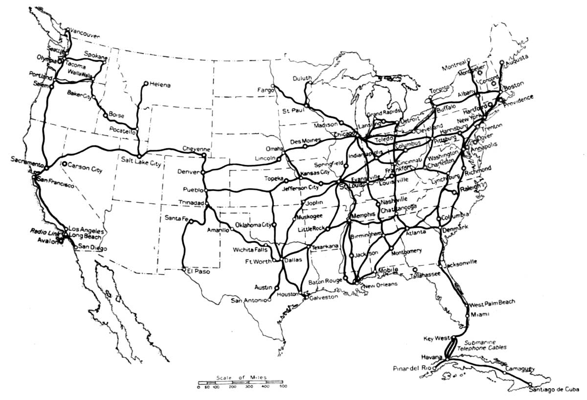
The system discussed in this paper includes three single-core continuously loaded submarine cables, each of which provides, in addition to a telephone channel, direct-current and carrier-current duplex telegraph channels. A description is given of the design and construction of the cables, of the method of superposing the various channels on each cable and of the terminal apparatus used for their operation. On April 11, 1921, commercial telephone service was inaugurated between the United States and Cuba over three submarine cables laid across the Florida Straits between Key West, Florida and Havana, Cuba. These submarine cables are the longest and most deeply submerged which are in use for telephonic communication. They are from 100.2 to 104.9 nautical miles (186 to 195 km.) in length and are laid in water which for a part of the route is about 1000 fathoms (1830 m.) in depth. The location of these cables and some of the important toll lines in the United States and Cuba are shown in Fig. 1. The cables were installed by the Cuban-American Telephone and Telegraph Company, an organization formed in 1919 by the American Telephone and Telegraph Company and the Cuban Telephone Company, for the purpose of providing telephone facilities between the United States and Cuba which would be suitable for connecting the telephone toll lines in the two countries.
The design of the submarine cables and the associated terminal equipment differs from previous systems because of the service which is furnished, the depth of water in which the cables are laid, and the length of the cables. The general features of this system will be indicated by the following summary of the requirements and the means which have been employed to meet them. To give the service desired over these cables, it was necessary that the telephone channels be suitable for use in circuits connecting points in the United States, such as New York and Chicago, 1557 and 2453 miles (2510 and 3940 km.) distant from Key West, with Havana and other points in Cuba, which is about 700 miles (1126 km.) in length. It was required also that the cables furnish, simultaneously with the telephone, a number of telegraph channels. These are provided partly by direct-current channels and partly by carrier-current channels [1] using frequencies above the telephone range.
Because of the depth of water and other conditions, the cables are of the single-core type, generally used for deep sea submarine telegraphy in which the return path of the circuit is through the sea. An important modification of this type has been made for these cables in order to make the circuits more suitable for telephone and carrier use. This consists in surrounding the insulation of the central conductor with a wrapping of copper tapes forming an uninsulated return conductor. In order to obtain the necessary efficiency for the telephone channels over cables of this length, the cables are “loaded,” that is, the inductance of the circuit is increased by the use of iron, and vacuum-tube repeaters [2] are used at the terminals for all connections over the cables.
To provide the desired services, required, in addition to laying the submarine cables, the extension in the United States of suitable toll lines to Key West and the installation of vacuum-tube repeaters in the Cuban toll lines. General Design Of System The construction of an open-wire land line along the causeway of the Florida East Coast Railroad which connects the string of small islands off the southern end of Florida, made it possible to land the cables at Key West and thus materially reduce their length. The landing points of the cables are on the western side of the entrance to the harbor of Havana and the southern side of the Island of Key West. This point in Havana is about a mile (1.6 km.) from the telephone toll office and that in Key West an equal distance from the existing telephone office. The distances from the cable landing points to the telephone terminal offices were kept as short as practicable in order to reduce the possibilities of interference from power circuits. The water in the Florida Straits, starting from Key West, increases gradually in depth. Five miles (9.3 km.) from shore it is about 40 feet (12.2 m.) deep, at 15 miles (27.8 km.) about 700 feet-(214 m.), and at 35 miles (65 km.) about 3000 feet. (915 m.) From that point on to within about three miles (5.6 km.) of Havana it is from 3000 feet (915 m.) to 6000 feet (1830 m.) in depth, being about a mile (1.86 km.) deep within five miles (9.3 km.) of Havana. These depths of water eliminated from consideration the use of a paper-insulated cable such as is commonly employed for telephone purposes on land or in shallow water. The most suitable construction for great depths is the submarine telegraph type of cable with an insulation of gutta-percha or similar material Previous gutta-percha or rubber-insulated submarine telephone cables have, in general, contained four cores arranged to provide three and sometimes four telephone circuits. Two of these circuits, the “physicals,” have been obtained directly from the two pairs of wires, one superposed circuit, the “phantom,” has been obtained from the two wires of each pair in parallel and in some cases a second superposed circuit has been formed by the four wires in parallel with a sea return. There was considerable question, however, in this case, whether a cable of this type could be sufficiently well balanced to keep the cross-talk between the two superposed circuits and the physical circuits low enough to permit of their simultaneous operation with the required amplifications. In comparing the four-core cable with a system consisting of three single-core cables, the following factors were important: First, the cross-talk factor; second, the lack of any experience with laying and repairing four-core cables in-water of these depths; third, the relative cost of the two systems; and fourth, the superiority of the single-core cables from the important standpoint of insuring continuity of service, at least for an initial installation of cables. A consideration of all these factors led to the adoption of single-core cables for this case. The inductance of a circuit may be increased by the periodic insertion of loading coils, or by “continuous” loading, which is the wrapping of iron wire or tape around the conductor. Because of the depths of water involved, the use of loading coils was impracticable. The placing of such coils in a cable causes, at the points of insertion, changes in the size and construction of the cable which are sources of weakness, both in connection with the stresses imposed on the cable in laying and repairing and also because of the necessity of making the cable resist the penetration of water, which at the deepest point reaches a pressure of over a ton per square inch (140 kg. per sq. cm.). The use of continuous loading for these conditions is advantageous not only mechanically in that it gives a uniform structure but also from the standpoint of keeping the terminal impedance of the cable uniform over the range of frequencies to be used. In repairing a coil-loaded cable in deep water it is practically impossible to maintain the regular spacing of the coils which is necessary for this uniformity of impedance. This uniformity is important in obtaining the close balance between the impedance of the cable and that of a network of impedance elements which is required for the two-way operation of amplifiers on the circuit. These cables were planned to provide New York-Havana connections for which a transmission equivalent of under fifteen miles of standard cable (cable having resistance of 88 ohms and capacity of 0.054 microfarad per loop mile) was desired. Since the operating equivalent of the New York-Key West portion of the circuit is about ten miles, the sum of the amplifications applied at the terminals of the cable must be within five miles of its equivalent. It was estimated that practicable cables could be obtained which would have transmission equivalents of about 25 miles of standard cable. This required that the amplifications at the terminals should average about ten miles. As the interference produced on such a cable by power systems, by other communication systems, and by natural disturbances and the cross-talk between the cables themselves are amplified also, the requirements for these factors were correspondingly more exacting. To reduce the interference at the terminals of the cables from local power circuits, two-wire metallic circuits are used from the telephone offices to the landing points and the submarine cables are connected to the land lines through transformers so that these lines are balanced to ground. The operation of direct current telegraph over the cables requires, however, that connections be arranged for carrying these telegraph channels around the transformers. Operation Of Single-core Continuously Loaded Cables The preliminary studies of the results to be expected with a loaded “grounded” cable circuit arranged for simultaneous telephone and telegraph operation indicated that satisfactory operation was dependent upon a number of factors regarding which little information was available. These included the effect of the sea return on the attenuation for alternating currents, the interference from natural electrical disturbances and from power systems at the terminals, the induction between cables and the interaction between currents of different frequencies resulting from their superposed fields in the iron used for loading. [3]
The effect of the sea return for the single-core cables used for submarine telegraphy has not been serious because it is practically negligible for the low frequencies involved. For direct currents, the cross-section of the return path is very large and its resistance low, even though the specific resistance of sea water is relatively high, of the order of ten million times as great as that of copper. For alternating currents, however, the return currents crowd in near the cable and the resistance of the return path is higher. This crowding effect of the return currents increases with frequency and consequently the resistance of the return path becomes greater. For frequencies in and above the telephone range the return currents are forced into the steel armor wires around the cable and into the layer of water just outside of the insulation. The small effective cross-section of the water involved and the losses in the armor wires cause the resistance of the return path to become a large part of the total resistance of the circuit and thus to have a large influence on the attenuation. The results of a few measurements of the sea return resistance for telephone frequencies, which had been made by British and French engineers, were published [4] in 1913 in an article discussing the factors involved in the use of single-core cables for telephony.
In connection with the plans for the Key West-Havana cables, a theoretical investigation [5] was made to determine how the resistance of the sea return is affected by the dimensions and construction of the cables and how it varies with frequency. This work in addition to giving a basis for investigating the effect of the dimensions of the cable and of the number and size of armor wires on the resistance of the sea return, made possible also the determination of the effect of a method proposed for reducing the losses in the sea return by providing a path of low resistance for the return current. It has long been the practise, when necessary to protect the insulation from the teredo, a marine borer, to wrap the gutta-percha insulation of submarine cables with a thin tape of brass or copper. This conducting tape suggested the use of a heavy copper tape, which, being just outside of the insulation, would be in the position which the high-frequency return currents would naturally seek to occupy. With this construction the lower frequency currents divide between the sea water, armor wires and the copper tapes, but as the frequency increases the part which returns through the tapes increases until finally for the upper frequencies in the telephone range practically all the current returns through the copper tapes. The resistance of these tapes becomes, therefore, practically the upper limit to the resistance of the return path. By making this path sufficiently low in resistance, it is possible to increase materially the efficiency of the cable. Furthermore, it is relatively inexpensive to place copper outside of the insulation, the main limitation to the amount being a mechanical one; namely, that as the tapes are made heavier and consequently stiffer, there is danger of damaging the insulation when the cable is bent. It was found that this idea of providing a conductive tape for the return was not new, [6] but investigation failed to show that it had ever been used or that any quantitative information had been published as to its effectiveness. This construction forms practically a concentric cable in which the outside cylinder is in contact with the water. In addition to its beneficial effect on the sea return, it is desirable also in that by reducing the external field of the circuit it decreases the induction between adjacent cables and also tends to decrease the effect of extraneous electrical disturbances.
In order to get directly experimental information regarding the interference and the effect of the sea return on submarine cables, permission was obtained from the British Columbia Telephone Company to make tests on their cable to the island of Vancouver, [7] from the Western Union Telegraph Company to test their cables landing at Key West from Cuba, and from the United States Government to make measurements on a cable from Key West to Sand Key, a small island about 8 miles (14.8 km.) from Key West on which are located a lighthouse and a weather bureau station.
The Vancouver cable is a four-core continuously loaded gutta-percha cable with a brass protective tape wound around the group of cores. Measurements were made of the sea return for grounded circuits, of the interference on grounded circuits and of the induction from a telegraph cable of the Canadian Pacific Railroad which parallels the telephone cable. In addition, tests were made to get some indication of the cross-talk which might be expected between the physical and superposed circuits in such a cable and of the regularity of the impedance in a continuously loaded cable. Tests were also made of the interaction between currents of telegraph and telephone frequencies. The superposition in the iron wire loading of the fields of these two currents has been found [8] to increase the attenuation of the circuit for telephone currents. This has been called the “flutter” effect.
The Western Union cables are single-core gutta-percha-insulated non-loaded cables with protective metal tapes. Measurements were made of the interference on the cables and also of the cross-talk between the cables. The Sand Key cable is a four-core non-loaded rubber-insulated telephone cable which has no protective metal tape. On this cable the sea return effect and the interference were measured. It should be noted that measurements cannot be made directly of the sea return resistance for telephone frequencies. The resistance of the grounded circuits was determined from measurements of the impedance of the circuit, from measurements of the attenuation and from such data regarding the constants of the cables as could be obtained from tests on short pieces. The resistance of the conductor itself was obtained from tests on metallic circuits. For the Vancouver cable, this included the effect of the loading on the resistance of the circuit for alternating currents. The magnitude of the sea return effect so determined checked closely the theoretical computations. In the case of the Vancouver cable this check involved taking into account the thin protective brass tape which had an appreciable effect. It was found also that the interference both from natural sources and from power systems would not be serious with amplifications even larger than those required on the Key West-Havana telephone cables. The tests for cross-talk between the cables at Vancouver which were about a mile (1.86 km.) apart for their length of about thirty miles (55.6 km.) gave no indication of induction from one cable to the other. The test on the Western Union cables which all terminated in the same hut at Key West gave a maximum cross-talk of less than 10 units at 1000 cycles (a unit of cross-talk being a ratio of current in the disturbed circuit to current in the disturbing circuit of 1 to 1,000,000). The flutter tests on the Vancouver cables showed that if the currents of the several channels were kept within reasonable limits, this effect should not cause trouble even for longer cables. The results of these tests removed any question of serious interference and cross-talk with single-core cables under the proposed conditions. They verified the serious effects of the sea return resistance, but by providing a check on the theoretical work, gave assurance that this could be applied in estimating the effect of employing heavy copper tapes to limit the resistance of the sea return. Cable Design
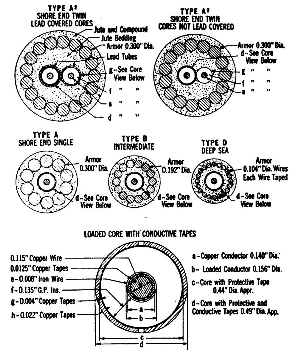
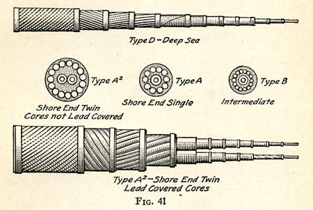
Conductor. To provide flexibility and security against breakage, it is customary to make the central conductor of a submarine cable not of a single solid wire but of a central wire surrounded either by a layer of copper wires or by a layer of thin copper tapes. In the present case the latter construction was used because of the smoother surface it provides for the loading wires. It also tends to give somewhat lower resistance and capacity for a given weight of copper. The actual conductor consists of a round copper wire 0.115 inch (2.92 mm.) in diameter surrounded by five copper tapes each 0.077 inch (1.96 mm.) wide and 0.0125 inch (0.32 mm.).thick. This conductor has a weight of 350 lb. (159 kg.) per nautical mile (1.86 km.). It was specified to have a resistance not to exceed 3.52 ohms per nautical mile at 75 deg. fahr. (24 deg. cent.) Loading. The cable is loaded with a single close layer of iron wire 0.008 inch (0.2 mm.) in diameter applied directly upon the central copper conductor. There are approximately 120 turns of this loading wire per inch length of the conductor. While an equally efficient cable for the transmission of telephone frequencies could have been produced at a lower cost by using a smaller conductor with heavier loading in the form of more layers or thicker iron wire or both, the requirements of the carrier telegraph made the lighter loading more desirable, as will be shown later. Insulation. The loaded conductor is treated with Chatterton’s compound and insulated with gutta percha mixture applied in three layers, thus forming a “core.” The amount of this insulating material is 315 lb. (143 kg.) per nautical mile which provides a wall thickness of approximately 0.135 inch (3.4 mm.). Because of the loading and the high frequencies for which the cable is used, low alternating-current conductance was specified for the dielectric, requiring the use of a special gutta-percha mixture. Return Conductor. As already stated copper tapes were applied to the outside of the core to diminish the losses caused by the sea return. In the actual construction a copper tape 1 inch (2.54 cm.) wide and 0.004 inch (0.1 mm.) thick is applied directly upon the core with short enough lay to provide safe overlap. Upon this tape are laid two heavier copper tapes, each 0.625 inch (1.59 cm.) wide and 0.022 in. (0.56 mm.) thick. These two heavier tapes are applied with a much longer lay, and are laid side by side with the edges not quite touching. The entire system of copper tapes, weighing approximately 850 pounds (390 kg.) per nautical mile, provides a return conductor with a direct-current resistance in the laid cables of approximately 1.65 ohms per nautical mile. The thin tape first applied directly on the core furnishes also the protection against injury of the core by the teredo. Sea Grounds. The main core with loaded central conductor and uninsulated return conductor, as described above, extends through the entire length of cable. In submarine telegraph cables it is the practise, in cases where it is especially important to reduce as much as possible all disturbances from outside sources, to construct portions of the cable near the ends with two cores so that the return part of the circuit is carried some distance out to sea before being connected to ground. In accordance with this practise, portions of each end of these cables were made with such two-core construction. In these portions the return or sea ground core has the same central conductor as the main core, no loading iron, the same amount of insulating material per unit length, and the thin protective copper tape but no heavy copper tapes. At the outer end of each of these sea ground cores its conductor is connected by electric welding to the conductive copper tape on the main core. Armoring. The armoring protects the core and gives tensile strength to the cable to permit its being handled for laying and for subsequent lifting in case of repairs. As-is usual, the size and number of armor wires are adapted to the location, taking into account such matters as depth, nature of bottom and water currents. The shore end portions, where because of relatively shallow water the cable is most likely to be injured, have the heaviest armor wire, which in this case has a diameter of 0.3 inch (7.6 mm.). The portions of the cable lying in the deepest water are armored with wire having a diameter of 0.104 inch (2.6 mm.). Intermediate portions of the cable have armor wires whose diameter is 0.192 inch (4.9 mm.). The 0.104 inch armor wire for the deep sea cable is a springy steel wire intended to give great tensile strength to the cable, while the heavier armor wire for the shore end and intermediate cable in shallower water consists of soft iron. The armor wire in all types of the cable is galvanized and is coated with preservative compound before being applied to the cable. The wires for the deep sea portions, in addition to being compounded, are individually wrapped with an impregnated fabric tape, which serves the double purpose of protecting the wire and making the cable more flexible by keeping the armor wires separated. Before the armor wires are applied, the core or cores are served with tanned jute yarn applied in one or more layers to form a bedding for the armor wires. In those portions of the shore end cable which have two cores, these are laid up together with a relatively long lay and with tanned jute in the interstices between the two cores, before applying the jute bedding for the armor wire.
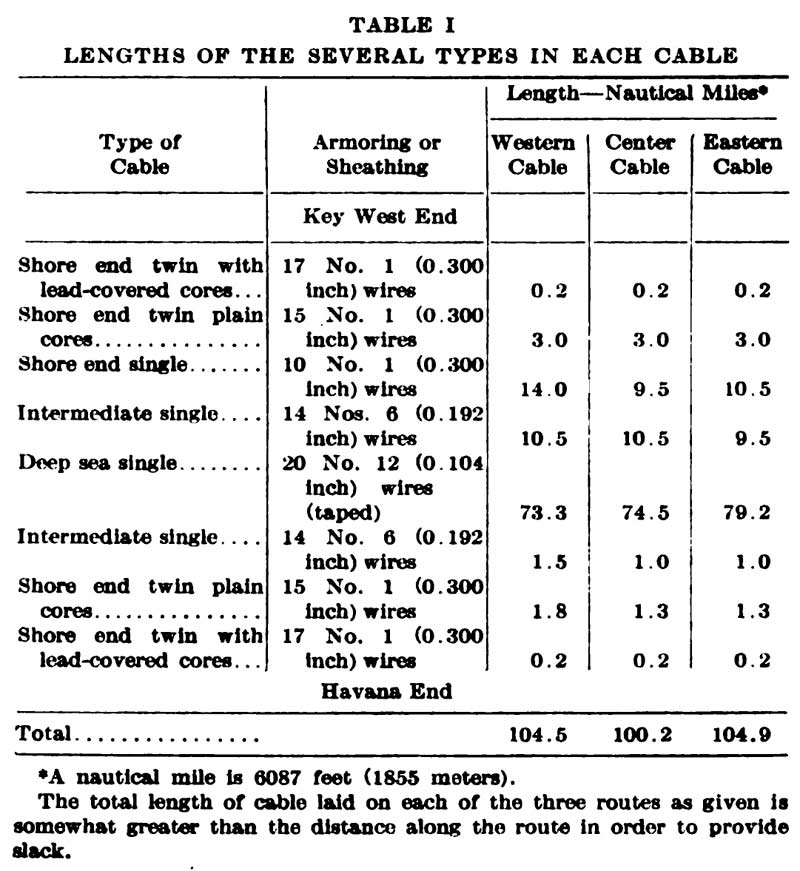
In the extreme shore ends a short length is made with each core covered with a close fitting tube of lead to protect it from light and air, which would tend to cause deterioration of the gutta-percha in those portions which may extend out of the water. The lengths of the several types differ somewhat in the three cables because of differences in the routes. In a general way the heaviest type of armoring extends from the shore to a point where the depth is approximately 100 fathoms (183 meters) and the intermediate type from this point to one where the depth is approximately 250 or 300 fathoms (457 to 549 meters), with the deep sea type in all the deeper parts. This arrangement carries the heavily armored cable much farther out from the Key West end than from the Havana end because 9f the much more gradual increase of depth of water at the Key West end. For the same reason the two-core or twin cable, which provides the return core for the sea ground, is carried out considerably farther at the Key West end. The approximate length of each type actually installed and the sequence of types are given for each cable in Table I.
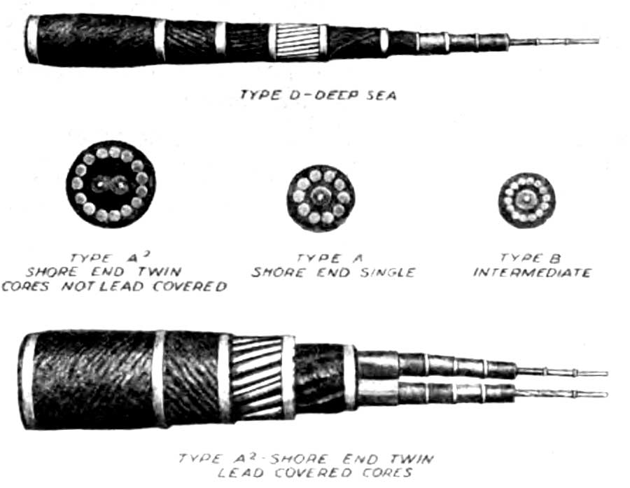
Some of the principal details of the design of the several types of cable with their relative dimensions are shown in the diagrams of Fig. 2. A photograph of specimens showing the appearance of the cables and some details of their construction is reproduced in Fig. 3. The over-all diameter of the largest shore end cable is approximately 2.4 inches (6.1 cm.) and that of the deep sea type approximately 1.2 inch (3.0 cm.). Cable Manufacture And Testing The cables were manufactured and laid by the Telegraph Construction and Maintenance Company, Limited, of London. Since the mechanical structure of these cables is in most respects similar to that of gutta-percha-insulated submarine telegraph cables, the manufacture was in the main carried on along the lines followed in making such cables. Briefly, this process is as follows: The central conductor is made by stranding around a copper wire a layer of finer copper wires or a layer of thin copper tapes. This conductor is then covered with the gutta-percha insulating material, generally applied in two or three layers to diminish the chance of a defect extending through the insulating envelope. Before applying the gutta-percha, the conductor is treated with a thin coating of Chatterton’s compound, to fill the interstices in the conductor and to increase the adhesion between the conductor and the gutta-percha. The insulated conductor so formed is known as a “core” and is manufactured in lengths generally ranging from 1½ to 3 nautical miles (2.8 to 5.6 km.), depending upon the weight of the core. In general it is necessary to manufacture heavy core in shorter lengths than light core. After the necessary inspection and tests the core lengths are served with tanned jute yarn, in one or more layers to form a bedding for the armor wires. In case the cable is to be protected against the teredo, the core, before being served with the jute bedding, is covered with a close overlapping layer of metal tape (generally brass). Either before or after being served with the jute bedding, the individual cores are joined together to form longer lengths. They then pass to the armoring or closing machine, which applies the armor wires. The galvanized armor wires, before being used, are coated with preservative compound and the armoring machine applies over the outside of the armor wires wrappings of tarred jute yarn or of a heavy burlap-like fabric known as “Hessian” band. Between the armor wires and these outer wrappings, as well as between and over the several wrappings, coatings of preservative compound are applied. From the armoring machine the cable is laid directly into the factory cable tanks, where it is treated with whitewash to prevent sticking, and where it is then kept submerged in water until it is transferred to similar tanks in the cable ship, for transport and laying.
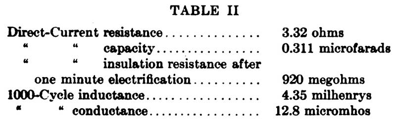
In the splicing of two lengths of cable, either at the factory or on the cable ship, a core joint is first made to unite the conductor and its insulation in the two portions of cable. Over this the jute bedding is then reapplied by hand, and finally the armor wires which had previously been opened up and laid aside, are laid back in such a way that the armor wire from one of the two pieces extends for a length of 15 feet (4.6 m.) or more over the armor wire of the other part. After laying the armor wire in place the splice is served with several tight bindings of galvanized iron wire and the whole covered by a continuous close binding of tarred yarn. In the manufacture of these cables the application of the iron loading wire to the conductor added an operation which, because of its relative slowness, largely determined the length of time required for manufacture. The heavy conductive copper tapes which are applied to the outside of the core could, because of their weight, be handled only in limited lengths of something like 200 feet (61 m.). Successive portions of this tape were joined together by welds. A soldering or brazing operation would have required the insertion of a dissimilar metal, which would increase the tendency to electrolytic corrosion when in contact with sea water. The cable in process of manufacture was subjected to the usual visual and manual inspections and electrical tests. The core was manufactured in individual lengths of approximately two nautical miles (3.7 km.) each. These individual core lengths, after 14 days' submersion in water, were tested at a temperature of 75 deg. fahr. for d-c. conductor resistance, insulation resistance and capacity. During the process of jute serving and armoring frequent electrical tests were made so that if any injury or fault should develop it could be detected and the defective part removed or repaired. Measurements of d-c. conductor resistance, insulation resistance and capacity were again made on the completed cable at various times during and after the manufacture, the loading upon shipboard and during the transport and laying of the cable. In addition to these tests, which are customary for all gutta-percha-insulated submarine cables, additional measurements were made on the present cables. The inductance and capacity of each length of core were measured by alternating-current methods. A large number of short lengths of core selected so as to represent all parts of the cable were measured for capacity and conductance at 1000 cycles per second and at 75 deg. fahr. It was found that the capacity as measured by a direct-current galvanometer method agreed within one per cent with the capacity obtained by measurements with alternating current of 50 cycles or 1000 cycles per second. Table II gives the average values per nautical mile of the several electrical constants as measured on the cores at a temperature of 75 deg. fahr. 14 days after manufacture.
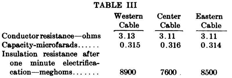
The corresponding values for the completed cable when laid are in some respects materially different. The insulation resistance is higher in the laid cables because it increased both with age and with the lower temperature at the sea bottom. The 1000-cycle conductance decreased with age but increased with the lower temperature—these two effects thus tending to offset one another. The inductance for the completed cable corresponds to that of a central loaded conductor with a concentric cylindrical return circuit, while the inductance measured on the individual cores was that of a gutta-percha-insulated loaded conductor in bifilar form. The conductor resistance is, of course, different because of the lower temperature of the laid cables. These extensive measurements were made to obtain data regarding the electrical properties of the cable and of the individual lengths of core. The data on the core lengths were used to determine their best sequence, in order to make the impedance at the ends of the cable as uniform as possible over the range of frequencies required for telephone transmission. Cable Laying The cable ship arrived at Key West February 7, 1921, and after certain preliminaries such as securing barges and tugs and making the necessary arrangements with the Government authorities proceeded with the laying operations. Where the water was deep enough the cables were laid directly from the cable ship which brought them from the cable factory to the Florida Straits. In shallower water the cables were laid from a barge or lighter towed by a tug. The actual sequence of laying each cable was as follows: First a length of approximately 6 or 8 miles (11 or 15 km.) was laid from a barge at the Key West end. The barge with its length of cable was brought as near as possible to the Key West cable hut. The extreme Key West end of the cable was pulled from the barge to the shore, laid in a trench on the beach and terminated n the hut. To facilitate this landing, the portion between the barge and the hut was supported at intervals by empty casks, to which the cable was tied by ropes, and thus floated in the water. After the landing of the shore end, the main portion of this cable section remaining on the barge, its length having been suitably chosen, was laid outward to a point having a depth sufficient for the cable ship. At this point the end was sealed and dropped to the bottom with an anchor attached to a marking buoy. Later this cable end was picked up by the cable ship and spliced to the next length, which was then laid by the ship from this point to the end of the intermediate type of cable, which as already stated reached to a point where the depth of water was about 250 or 300 fathoms (457 or 549 meters). Again the end was sealed and laid overboard with an anchor and a marking buoy. Next a short length of shore end cable was laid by barge from the Havana cable hut outward and its end lifted to the ship and there spliced to the main length of cable, which was then laid by the ship from this point near Havana to the point where the buoy marked the location of the end of the intermediate cable previously dropped. After lifting this buoyed end the final splice was then made on the ship connecting the buoyed end to the main cable on the ship and the work of laying completed by dropping the final splice overboard. After the completion of the laying of the three cables the final acceptance tests were made at the ends of the cables in the Key West cable hut. These tests covered only such measurements as are customary on submarine telegraph cables; i.e., measurements of direct-current conductor resistance, direct-current insulation resistance and direct-current capacity. They were intended merely to determine these direct-current properties and to insure the electrical integrity of the cables after completion of the laying. The results of these tests are shown in Table III which gives values per nautical mile:
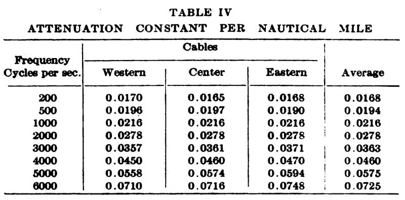
These tests were completed the evening of February 25, 1921, and on February 26, 1921, the surplus and spare cable was delivered into the storage tank at Key West and the cables were formally accepted. Cable Characteristics In view of the fact that the return circuit of the single-core cable includes the sea water, the operation of the cables could not be determined accurately until they were laid. The lengths of the laid cables are such that determinations at telephone and carrier frequencies of the primary constants, resistance, inductance, capacity, and conductance can not be made directly. The secondary constants, the impedance and attenuation, can be measured and these data together with the results of the tests on short pieces used to estimate the primary constants. After acceptance, extensive alternating-current measurements were made on the three cables, covering the range from about 100 to 6000 cycles. These tests included determinations of the ratio of the current received at one end of the cable to that sent in at the other and measurements of the impedance at each end of each cable with the far end closed through the characteristic impedance of the cable. From these measurements of the ratio of the “received” current I2 to the “sent” current I1, the attenuation constant [alpha] per nautical mile of each of the cables was obtained from the relation
where L is the length in nautical miles. These values for a range of frequencies are given in Table IV. It is seen that the values for the three cables do not differ materially. The average of the attenuations for the three cables is shown also in Fig. 4.
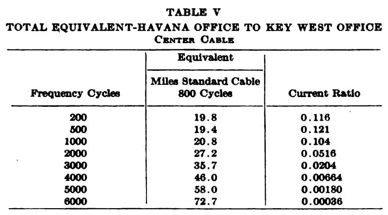
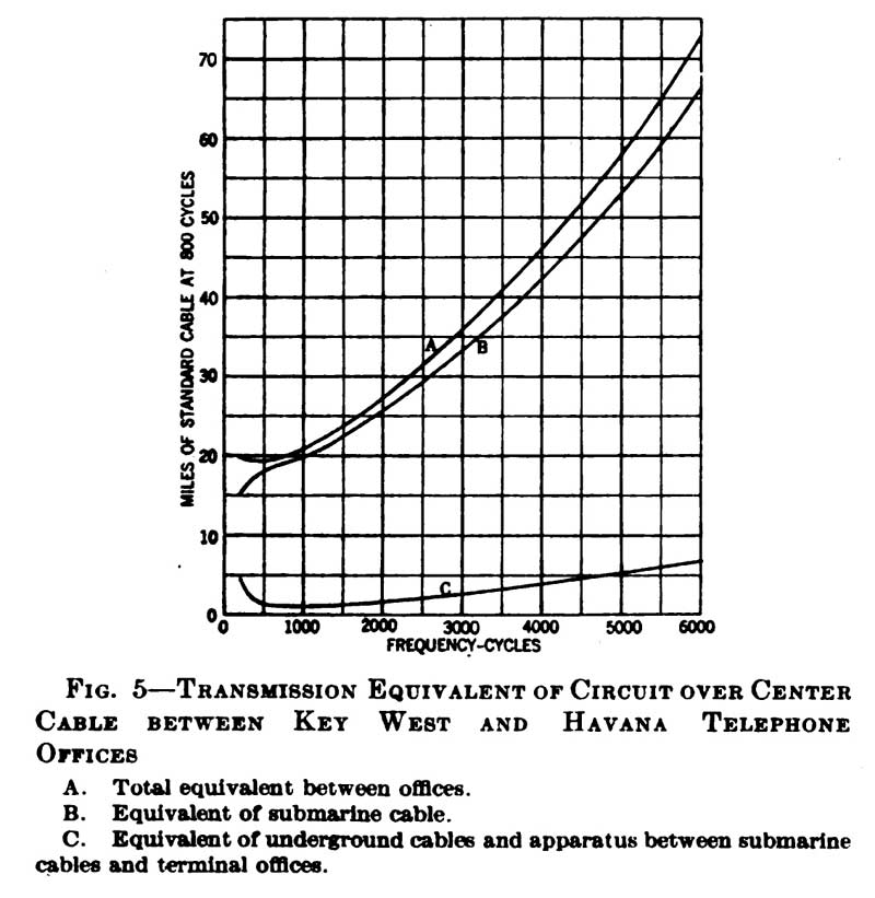
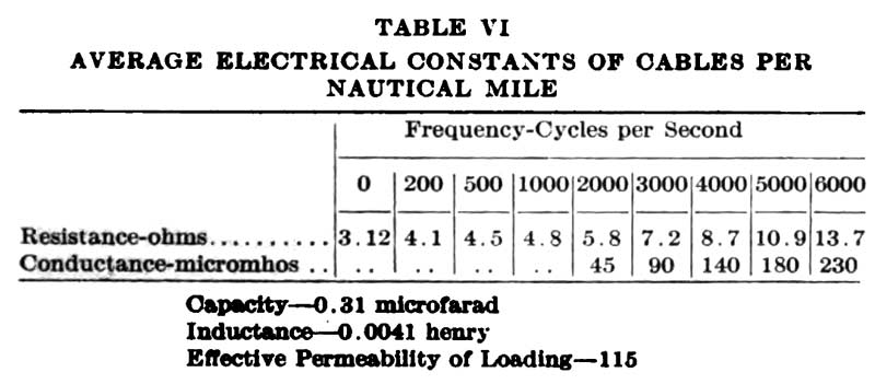
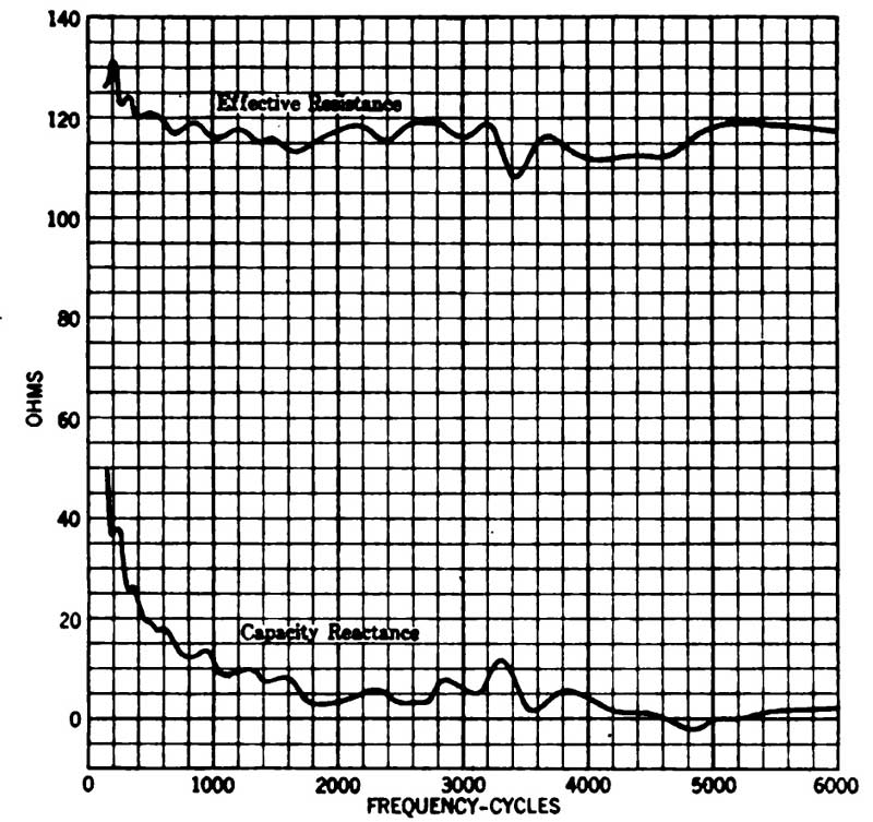
The transmission equivalent of the center cable, which is the shortest, is shown in terms of miles of standard cable at 800 cycles (attenuation of one mile of standard cable at 800 cycles is 0.109; in Fig. 5. This figure gives in addition the combined equivalent of the compositing apparatus in the two huts and the land cables at the two ends between the cable huts and the offices, and also the total equivalent of the circuit from the Key West office to the Havana office. Table V gives the total equivalent of the circuit over the center cable between the two offices and the corresponding current ratios. The variation of the resistance and reactance components of the impedance of the cable is illustrated in Fig. 6. The deviations of these curves from those that would be obtained if the cable were absolutely uniform throughout its length are under 3 per cent. From these measurements, from the tests in the factory and from computations, it is possible to estimate fairly closely the constants of the cables. The average of these constants for the three cables is given in Table VI. The conductance is not given for frequencies of 1000 cycles and lower as its effect for this range is so small as to make determination of its value practically impossible under the conditions.
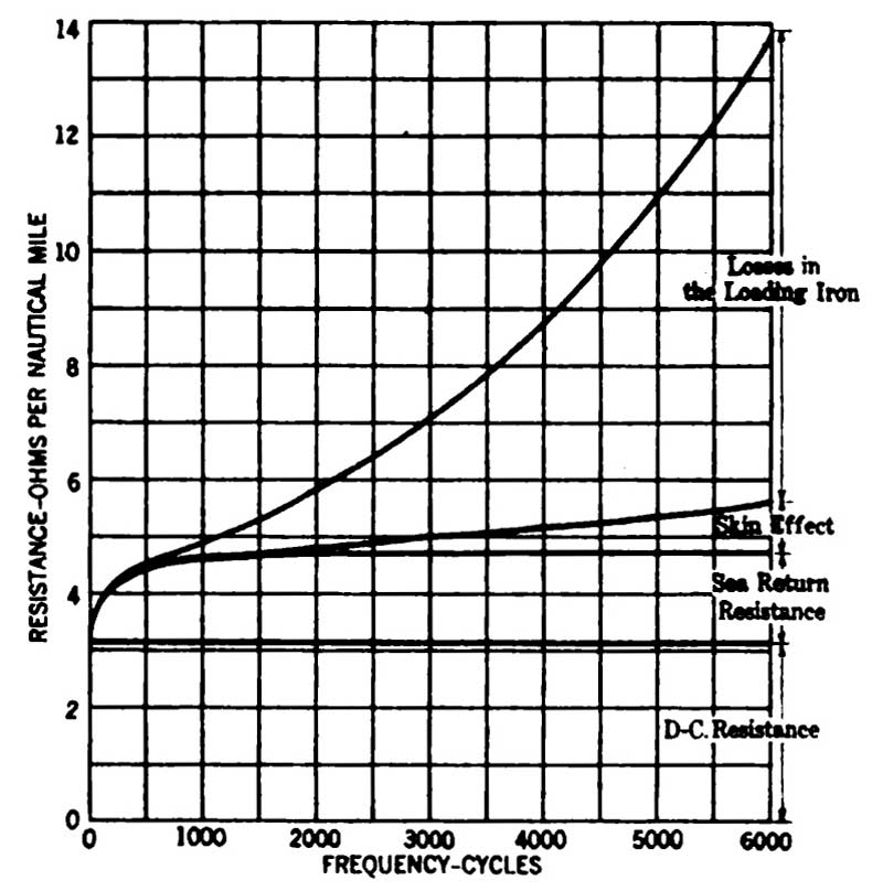
Estimates were also made of the distribution of the resistance in the circuit for a range of frequencies. The curves of Fig. 7 give average values for the three cables of the d-c. conductor resistance, the increase of the conductor resistance with frequency due to skin effect, the resistance of the sea return and the resistance -added to the circuit by losses in the loading iron. The large part contributed by the loading at the higher frequencies shows why it is desirable to use the light loading where carrier frequencies are to be transmitted. The use of iron wire 0.012 inch in diameter would have increased the resistance added by the loading by about 55 and 90 per cent at 3000 and 5000 cycles respectively above the values obtained with 0.008-inch wire. These increases in resistance, in spite of the increase in inductance resulting from this change, would have increased the attenuation by 33 and 65 per cent at these frequencies.
Estimates of the resistance of the sea return which would have been obtained in the deep sea portion of the cable if no copper tapes had been provided give values of 4, 6.5 and 8 ohms per nautical mile at 1000, 3000 and 5000 cycles. The resistance actually obtained with the copper tapes does not exceed 1.7 ohms at 5000 cycles, as shown on the curves of Fig. 7. The greater values would have increased the attenuation by approximately 30 per cent at 1000 cycles and by 50 per cent at the two higher frequencies.
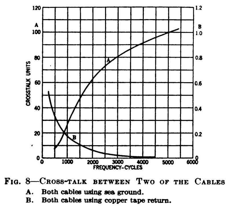
The results of the measurements of the cross-talk obtained at Key West between two adjacent cables are shown in Fig. 8. It will be noted that the cross-talk between the cables when the connection is made to the copper tapes is less than one per cent of that obtained when the connection is made to the insulated sea ground conductors. Measurements of the interference on these cables showed this to be practically negligible. As might be expected, the interference of frequencies in the d-c. telegraph range was greater when using the return tape than when using the sea ground. The interference at the telephone and carrier channel frequencies was, however, many times greater when using the sea ground conductors, the interference when using the return tape being so small as to be negligible even with amplifications larger than required for operation. The maximum interference currents obtained with the tape return were less than one microampere and this was largely 180-cycle current, which was probably produced by a harmonic in a power circuit near the terminal.
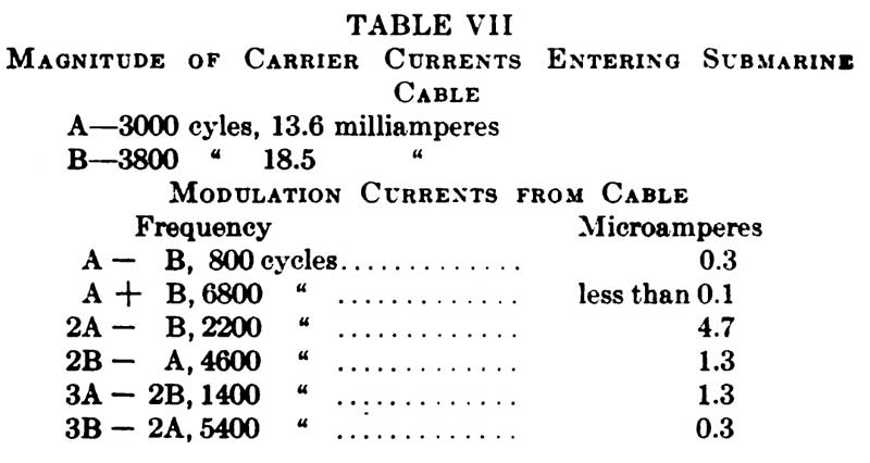
The results of the cross-talk and interference tests confirm the expected operation of the heavy copper tape return, that is, that practically all the current of frequencies in the important part of the telephone range and above would return through the tape. On the same basis the tape acts as a very effective screen against interference currents of these frequencies. Measurements of the flutter effect between the d-c. telegraph and the telephone channel showed that the passing of the telegraph currents over the cable simultaneously with currents of frequencies in the telephone range, reduced the magnitude of the received telephone current by only a small fraction of one per cent. The maximum value of the d-c. telegraph pulses was about 14 milliamperes. The maximum effect on the carrier telegraph operation of the d-c. telegraph and the telephone together was a reduction of under 3 per cent in the magnitude of the received carrier currents. This was inappreciable in the operation of the carrier system, as the receiving circuit is designed to be saturated with the normal incoming current, so that slight changes in the sent currents or changes in the circuit efficiency have no effect on its output. Investigation was also made of “modulation” effects in the loading. Where two currents of different frequencies, A and B, are superposed on the circuit and hence have their fields superposed in the iron wire loading, currents of other frequencies are set up in the cable as a result of the non-linear characteristics of the iron. The frequencies of these modulation currents are the sums and differences of the frequencies A and B and of their various harmonics, such as A ± B, 2A ± 2B, 2A ± B, A ± 2B, 3A ± 3B, 3A ± 2B, 3A ± B, A ± 3B, and so on. The superposition of additional currents of frequencies different from A and B produces of course additional resultant modulation currents. The even order modulation currents, that is, those of frequencies for which the sums of the coefficients of A and B are even numbers, such as A ± B and 2A ± 2B, are due largely to magnetic bias of the loading and are therefore materially affected by the amount of direct current flowing in the circuit. The odd order terms, such as 2A ± B, A ± 2B and so on, are produced by the non-linear force-flux characteristic of the iron and are less affected by the direct current. The principal modulation currents found in the work on the cable were those of frequencies A ± B, 2A -B, 2B - A, 3A - 2B, and 3B - 2A. Others were present but were either so small in magnitude or so high in frequency as to be negligible compared to the above. The measurements of the small modulation currents necessarily involve highly selective circuits, large amplifiers and special circuit arrangements in order to prevent the currents causing the modulation from entering the circuit measuring the modulation currents and also to eliminate the modulation effects in the measuring apparatus itself. For the present arrangement of channels with the 3000-cycle carrier flowing into the cable at Havana and the 3800-cycIe carrier at the Key West end the modulation currents produced by the carrier telegraph currents are very small. The 2A - B term, which is the largest, is only 0.2 microampere. If the two carrier currents are sent into the cable at the same end, however, the modulation currents while still small are appreciable, as shown in Table VII.
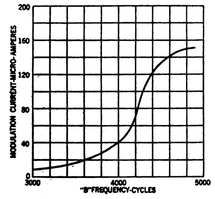
While for these arrangements the modulation effects were found to be so small as to cause no serious interference, they may under some conditions become large enough to require consideration, particularly in connection with increasing the number of carrier telegraph channels over the cables. In that case, these modulation currents affect the number of channels, the current levels and the frequencies which can be used. This effect appears not only as noise in the telephone but also as interference between carrier channels. As an illustration of the magnitudes which may be obtained, Fig. 9 shows the 2 A-B term for a constant A frequency of 2500 cycles with the B frequency varying from 3000 to 5000 cycles. The magnitudes of both A and B are 30 milliamperes into the submarine cable at the same end, the modulation currents being measured also at that end. It is seen that for the lower frequency values of 2 A-B, the magnitudes are comparable with those of components of the telephone currents on the cable.
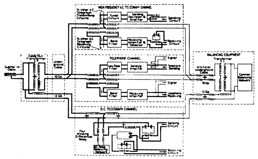
Compositing Arrangement At Terminals For the initial operation over the cables, arrangements were made and apparatus provided for two duplex telegraph channels and a telephone channel over each of the three cables. One of the telegraph channels is furnished by the direct-current system and the other by the carrier-current system using frequencies above the voice range. In addition to the above, a signaling channel required for the operation of the telephone channel uses currents of frequencies in the voice range. It is possible to employ this range since it is not required simultaneously for signaling and talking. The general method of superposing these channels on the cable and connecting them to the terminal apparatus is shown in Fig. 10. As the channels are required to operate in both directions, the usual balance system is provided for each channel to prevent the currents sent out at one terminal from operating the receiving apparatus at that terminal. The balance system consists essentially of a “bridge transformer” and a network of impedance elements designed to simulate the impedance of the line for a range of frequencies. The bridge transformer is a transformer with three windings, from two of which accurately located center taps are brought out. This transformer is thus suitable for providing a Wheatstone bridge circuit in which the two windings having mid-point taps serve as ratio arms. The transmitting amplifier output is connected to the mid-point taps and the receiving amplifier input to the third winding of the transformer. With the balancing network adjusted to have an impedance equal to that of the line, the transmitting amplifier does not send current into the receiving amplifier.
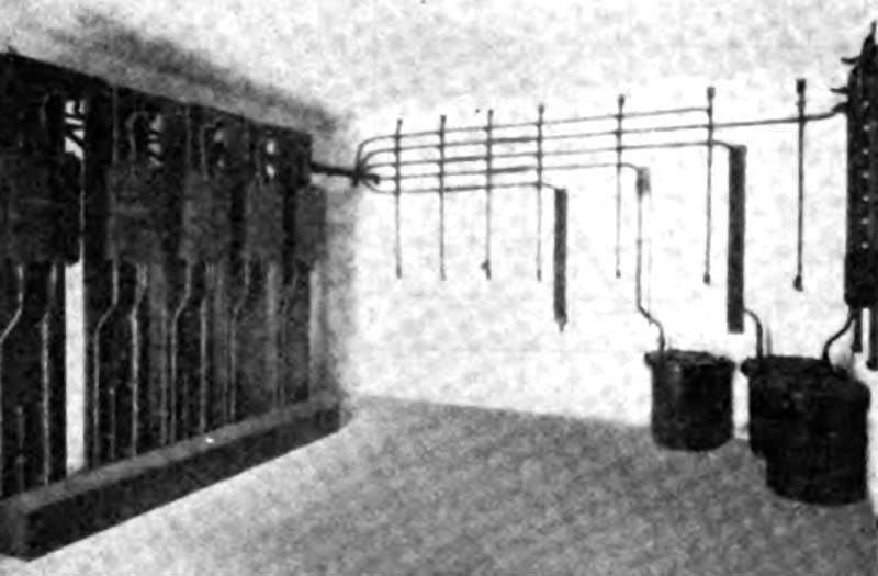
Filters or selective circuits are placed in the sending circuits to insure that the outgoing currents of any channel do not contain frequencies which will interfere with the other channels, and in the receiving circuits to admit only those currents in the proper frequency range. At the cable hut the submarine cable is connected by a 1 to 7 impedance ratio, specially balanced transformer to a two-wire underground cable circuit of No. 10 A. W. G. (diameter 0.102 inch, 2.6 mm.) conductors. Across the cable side of the transformer is bridged a No. 13 A.W.G. (diameter 0.072 inch. 1.8 mm.) twowire circuit for the direct-current telegraph channel. The No. 10 circuit carries the telephone and the carrier telegraph channels to the office. The transformer serves to insulate the grounded submarine cable from the land cable and thus renders the latter less susceptible to interference from power systems. It also steps up the impedance of the cable to meet the impedance of the telephone and carrier channel terminal apparatus and aids in keeping the d-c. telegraph currents out of the higher frequency channels. This latter function is assisted by the condenser at the mid-point of the cable side of the transformer. The telephone and carrier apparatus is connected in parallel to the No. 10 A.W.G. underground cable circuit. Each set of equipment contains a bridge transformer which separates the sending and receiving circuits. These two bridge transformers are connected in parallel both to the cable and to the common balancing network so that the sending circuit of either channel will not send current into the receiving circuit of the other channel. The sending channels are not so balanced against each other, but since each contains a filter or tuned circuit which presents high impedance to currents from the other sending circuit, little current flows from one sending circuit to the other. The receiving side of the telephone is protected by balance against the sending side of the telephone and by both balance and selectivity against the sending side of the carrier channel. The d-c. telegraph channel is also in parallel with the telephone channel but is connected to it at points different from the carrier channel. The inductance coils and condensers in the d-c. channel constitute a low-pass filter which transmits frequencies from zero to about eighty cycles. This channel has one branching arrangement which is designed so that the receiving circuits of the higher frequency channels are balanced against both the outgoing telegraph currents and the disturbances produced in the relay windings by the operation of the relay armature under the actuation of the received signals. It has also the second branching arrangement in the windings of the receiving relay, to separate the sending and receiving telegraph circuits. This requires the second balancing network which is connected with this relay. It will be noted that associated with the main balancing network shown in the right of Fig. 10 is a duplicate of all the apparatus and circuits between the terminal apparatus and the submarine cable. The balancing network itself is adjusted to simulate the impedance of the submarine cable over the range of frequencies required for the operation of the telephone and telegraph channels, particular attention being paid to have it meet this impedance for the range of the telephone channel. Because of the degree of uniformity obtained in the impedance of the cables, it was possible to get a very good simulation with a simple network of three impedance elements. If the cables had been less uniform it might have been necessary to employ a multi-section artificial cable such as is used with long submarine telegraph cables. The balancing transformer and artificial underground cable are adjusted to match the impedances of the corresponding elements in the cable circuit. By this means, it is possible to obtain a balance at the terminals of the bridge transformers which for any frequency in the telephone range is within 3 per cent of being perfect, thus making it possible to use high amplifications with this channel. The degree of balance is only slightly poorer in the carrier telegraph range. Since the attenuation in the range available for carrier telegraph use is greater than that in the telephone range and the amplifications therefore necessarily larger, the land-line carrier telegraph practise was followed in not relying entirely upon the balance to prevent interference between the outgoing and incoming carrier currents but in using different frequencies in the two directions with the selective circuit and filter in the sending and receiving branches tuned respectively to these different frequencies. For operation from Havana to Key West a carrier frequency of 3000 cycles is used and for the opposite direction a carrier frequency of 3800 cycles. The arrangement of the terminal apparatus in the cable hut s shown in Fig. 11. Each of the submarine cables is terminated in one of the boxes at the left, which are water-proof. The submarine cable enters the box from below, the two cores entering through separate bushings. The underground cable circuits from the office are brought into the boxes from above. Cables also lead from these boxes to the pots at the right which contain the transformers, condensers and inductance coils located at the hut. A tie cable enters all the boxes from below to make possible cross-connection of the circuits and apparatus.
Terminal Equipment Amplifiers and signaling apparatus for the telephone circuits and terminal apparatus for the telegraph and carrier telegraph channels are provided for each cable at the terminal offices in Havana and Key West. Although these terminal units in general resemble those developed for similar uses on land-line telephone and telegraph circuits, they differ in many respects because of the high attenuation of the submarine cables and the different methods of operation required on these circuits. The general theory and operation of telephone repeaters [9], carrier telegraph apparatus [10] and vacuum tubes [11] have been described in various publications. Those features in which the cable apparatus is similar to earlier types will not be discussed here in detail.
The terminal apparatus was designed, manufactured and partly installed before the laying of the cables in order that service might be given as soon as possible after they were laid. The design of the apparatus was based on the estimated characteristics of the cables but in order to provide for satisfactory operation, in case the attenuation and interference should exceed the expected values, the terminal apparatus was made adjustable over a wide range of amplifications and current levels.
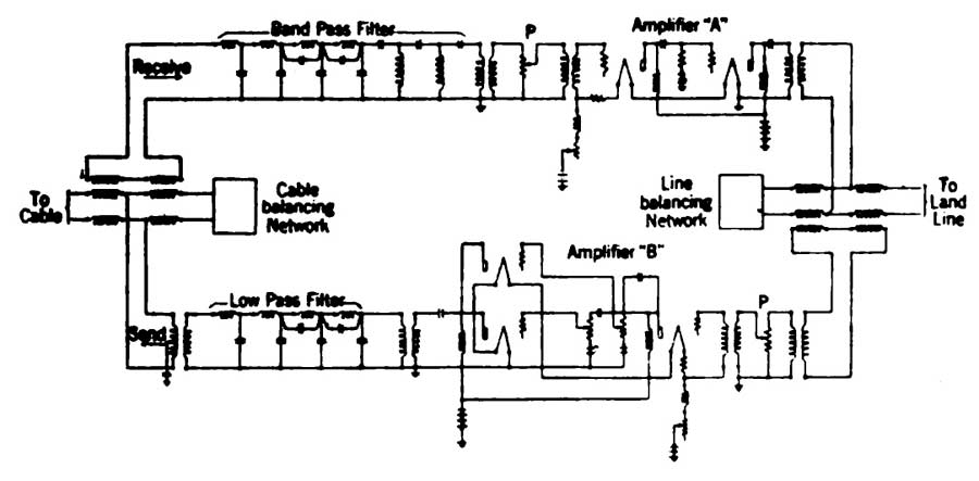
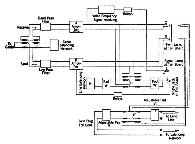
Telephone Circuit The telephone channels of the cables are connected to the land lines through bridge transformers and amplifiers as shown in Fig. 12. The third winding of each bridge transformer is connected through an amplifier to the center points of the line windings of the other bridge transformer, thus forming the two-way, two-amplifier repeater circuit generally called a “22type” circuit [12]. Since a close and constant balance has been secured between the cable and its network, as pointed out above, the repeater may be worked with large gains [13] even when the balance between the land line and its network is not close. Such is the case in terminating connections where the land end of the repeater is connected through the toll switchboard to subscribers’ lines, as in calls to or from subscribers in Havana or Key West, without intervening toll lines of considerable length which could be balanced more closely. Networks are provided to balance the average subscribers' lines as well as possible. When the repeater is to be connected to land lines of considerable length, networks of the general character described in an earlier paper [14], which provide a better balance for these lines, are used. Such networks are provided for use with the circuits extending north from Key West and also for use with the toll circuits in Cuba.
The repeaters combine the operating characteristics of “through-line” and “cord-circuit” repeaters. A through-line repeater is one which is permanently connected in a toll line, the whole forming a through-line circuit, no part of which is under the control of an operator at the repeater station. In a cord-circuit repeater the two line ends of the repeater circuit appear at the toll switchboard as plugs and this repeater cord circuit may be used to connect toll lines which terminate in jacks in the switchboard. Such a repeater is arranged so that the gain can be adjusted by the toll operator to the value specified for the circuits which it is used to connect. In the Key West and Havana repeaters the cable bridge transformers, the cable balancing networks and the amplifiers are permanently connected to the cables, the repeaters being thus through-line in character on the cable side. The repeaters at Key West on the through circuits are permanently connected to the land lines and their balancing networks, with certain arrangements for patching to be noted below. Such circuits are shown schematically in heavy lines in the upper part of Fig. 13. At Havana, and at Key West on the one circuit terminated there, the land sides of the repeaters terminate in the switchboard, so that these repeaters have some of the features of cord-circuit repeaters. These so-called “terminating connections” are shown in schematic form in Fig. 14. In the terminating as well as in the through-line circuits, the gains of the amplifiers are adjusted by means of the potentiometers P and P' shown in Fig. 12. These are set at the proper values by the repeater attendant. The control at the switchboard of the effective gains of the terminating repeaters is obtained by means of artificial lines or pads on the line and network sides of the bridge transformers H and H’ as shown in the lower part of Fig. 14.
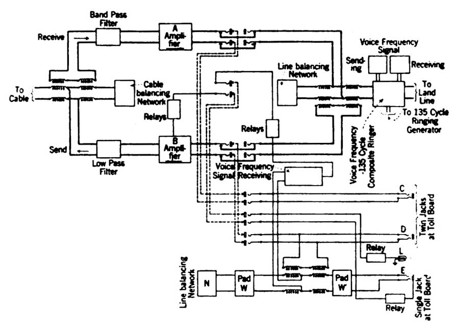
In the terminating circuits, the land side of the repeater appears at the switchboard in both a single-jack and a twin-jack termination, as shown in Fig. 14. The single-jack termination is used for connections to local subscribers' loops and the twin-jack arrangement for connection to land toll lines. A call coming over the cable, indicated by the lighting of the signal lamp L, is answered with a single-plug toll cord, the plug being inserted in the jack E. If the call is intended for a local subscriber, the other end of the cord is plugged directly into the local circuit at the switchboard. This circuit is balanced by a network N designed to balance the average local connection. When the circuit is not in use the net work N is disconnected and the two equal pads W and W preserve the proper impedance balance on the two sides of the bridge transformer H, so that singing in the repeater circuit is prevented. The insertion of the cord-circuit plug in the single jack E operates a relay which connects the network Ar in place. When connection to the subscriber’s instrument has been completed, the current from the central battery through his transmitter operates a train of relays which reduces the transmission loss introduced by the pads. The same change in the pads is produced when the operator, by throwing her talking key, causes current to pass through her transmitter. If the call is routed to a toll line, the connection is made by the insertion of a “twin-lug toll cord” in jacks C and D, which disconnects the single jack circuit automatically. The twin plug at the other end of the cord is inserted in the jacks connected to the desired toll line and its balancing network. The circuit of this twin plug toll cord is shown schematically in the lower part of Fig. 14. In this case the operator may control the effective gain of the repeater by a key which changes the number of sections in the adjustable pads V and V. In through-line use of the repeaters both amplifiers are continuously supplied with filament current and are maintained in operating condition. In cord-circuit or terminating use the amplifier which receives from the cable is kept in operating condition in order that signals may be received. When a connection is made through either the single- or double-jack circuits, relays are operated which cause current to be supplied to the filaments of the sending amplifier. No current is supplied to this filament circuit except when a connection is established. In view of the fact that it may sometimes be desired to terminate temporarily at the Key West switchboard any one of the through-line circuits, the repeater circuits have been arranged to facilitate this. It will be noted in Fig. 13 that the through-line circuits pass through a group of jacks. These are located in the “jack panel,” a unit in which are terminated all the principal circuits associated with the cable. When the connections indicated by the dotted lines are made the resulting circuit is the same as that of Fig. 14. In order to protect the telephone apparatus against interference due to the telegraph channels, a filter system is connected in the telephone circuit between each amplifier and the cable bridge transformer. The filter in the receiving branch (Fig. 12) freely passes the range of frequencies (250 cycles to 2300 cycles) assigned to the telephone channel and greatly attenuates currents of all other frequencies. The filter in the sending branch prevents the passage of currents of frequencies which would interfere with the carrier telegraph channel.
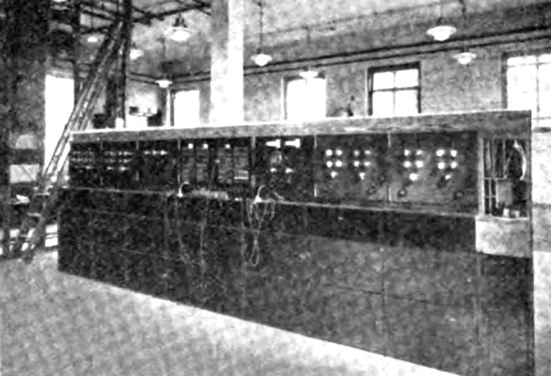
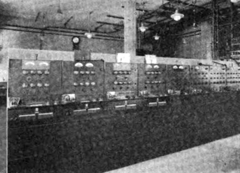
The amplifiers, filters and other equipment of each repeater are mounted in a unit panel. These, together with the panels containing the terminal equipment associated with the other communication channels, are arranged in a double row in each terminal office. One of these rows is shown in Fig. 15. Four of the panels, two at each end, are repeater units, three of these being associated with the three cables. Owing to the importance of these circuits a spare unit has been provided to insure against interruption of service. Signaling Systems The signals for the telephone channels are transmitted over the cables by a "voice-frequency" signaling system, which involves the generation, transmission and reception of an alternating current, the frequency of which changes abruptly from 950 cycles to 1300 cycles and back, this alternation of frequencies taking place at the rate of 16 cycles per second. Signals are transmitted over the land lines north from Key West and over the toll lines terminating at Havana by means of the usual 135- and 16-cycle currents. By means of a ringing key in the toll cord circuit, the operator at one end of the cable causes the voice-frequency current described above to be sent out by the signaling oscillator, a vacuum-tube oscillator of the usual type arranged so that the capacity in the oscillating circuit is changed 32 times a second. This sends out alternately currents of the two different frequencies through the sending amplifier B (Fig. 14) to the cable. At the other end of the cable these currents flow into the receiving side of the repeater and through the amplifier A. If the telephone circuit is terminated at this point, part of the amplified signaling current passes into the receiving circuit for voice-frequency signals as can be seen from Fig. 14.
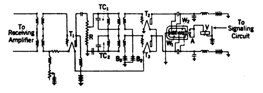
The details of the voice-frequency signal receiving circuit are shown in Fig. 16. The input impedance of this circuit is high so as to produce no appreciable loss in the telephone transmission circuit across which it is connected. The incoming signaling currents are amplified by the tube T1, from which they pass into the high resistance R. Connected in series across this resistance are two tuned circuits TC1 and TC2, of which one is tuned to 950 cycles and the other to 1300 cycles. Each tuned circuit is connected through a transformer to the input side of a vacuum-tube rectifier. The grids of the tubes T2 and T3 are made just sufficiently negative by means of the batteries B2 and B3 so that there is normally no current flowing in the plate circuits of the tubes. The tubes thus function as detectors of incoming currents. When 950-cycle current is impressed on the circuit TC1 a voltage is applied to the grid of tube T2 causing current to flow through the relay winding W1. The next instant rectified 1300-cycle current passes through winding W2. The armature A of the polarized relay then vibrates back and forth at the rate of 32 times a second, thereby interrupting the current through the relay V. The armature of this relay therefore falls back, lighting the signal lamp L (Fig. 14) at the switchboard.
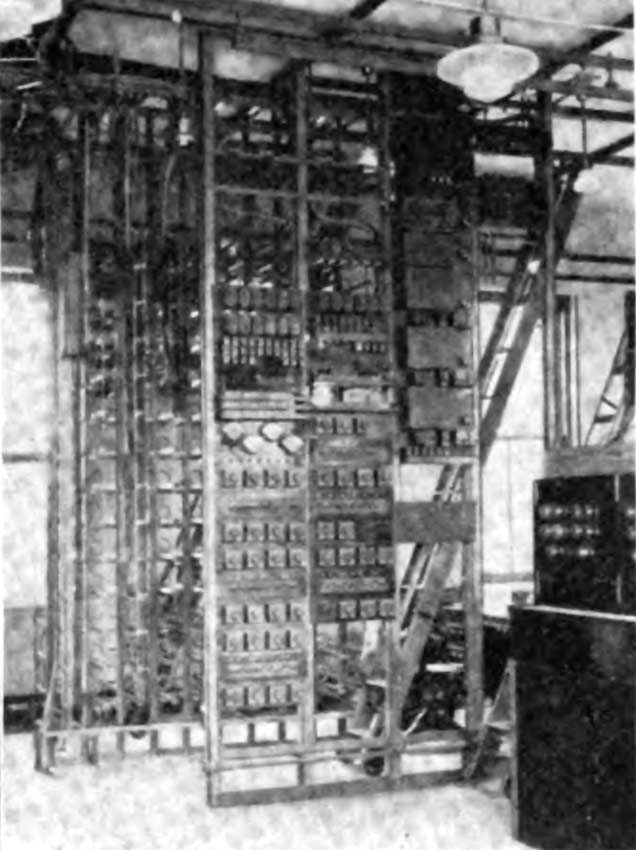
In the through-line circuits at Key West, such as the Havana-New York circuit, as shown in Fig. 13, the voice-frequency signaling current coming from the cable causes 135-cycle signaling current to be sent out automatically on the north-bound land line by a special type of “composite ringer” indicated in the upper right-hand part of this figure. The voice frequencies are received by a circuit similar to that just described and operate a relay which connects a generator of 135-cycle current to the land toll line, thus sending out this type of signaling current to call the distant operator. In through-line calls from the north 135-cycle current is sent over the land toll line to Key West. Here it enters the composite ringer and operates the voice-frequency sending set which puts on the cable the voice-frequency currents described above. These currents are received at the Havana toll office in the circuits shown in Figs. 14 and 16 and cause the operation of the signal lamp L at the toll board. The receiving circuit for voice-frequency signals which is used in the case of terminating connections is included in the repeater unit. The composite ringers, which in the case of through-line circuits effect the change from voice-frequency signaling on the cables to 135-cycle signaling on the land lines, are mounted on the upper right-hand side of the relay rack shown in Fig. 17. Below the composite ringers are two oscillator sets for furnishing the 950- and 1300-cycle currents for telephone signaling over the cable, one of these being a spare unit. Carrier Telegraph A carrier telegraph terminal unit is permanently associated with each cable at both the Key West and Havana Offices. The circuits in the units used at
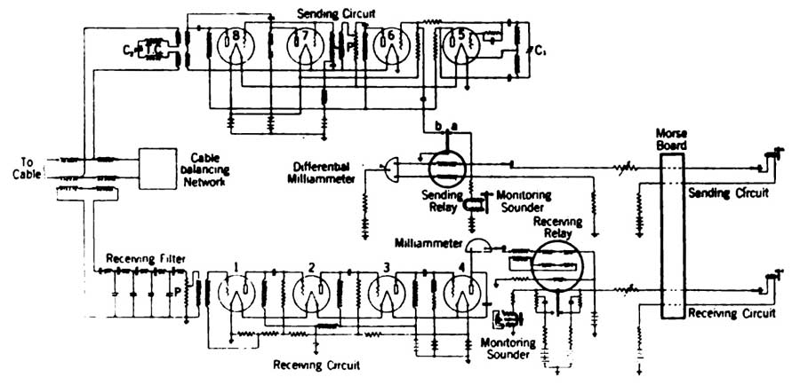
The operation of the carrier telegraph channel may be stated briefly as follows: Direct-current telegraph signals received from a subscriber’s loop or other land line, actuate the sending relay in the carrier set, causing the oscillator to send through the cable high-frequency alternating current, interrupted in conformity with the signals. This alternating current enters the carrier receiving circuit at the other cable terminal, is rectified and actuates the receiving relay which sends direct-current telegraph signals into the associated land circuit. The arrangement of the complete carrier terminal circuit is shown in Fig. 19. The details of carrier telegraph circuits have been described in an earlier paper [15] and only the outstanding features will be mentioned here. The armature of the sending relay [16] is normally held against the contact a. Under this condition the oscillator transmits a steady high-frequency current through the amplifier and tuned circuit to the cable. When a “spacing” signal is transmitted over the subscribers' sending loop, the armature of the sending relay moves to contact b which shunts the sending amplifier, interrupting the flow of high-frequency alternating current to the cable. A “marking” signal causes this armature to move to contact o, thus sending the high-frequency current out upon the cable. The sending relay, therefore, causes the signals transmitted over the land line by direct current to be converted into pulses of alternating current which are sent into the cable.
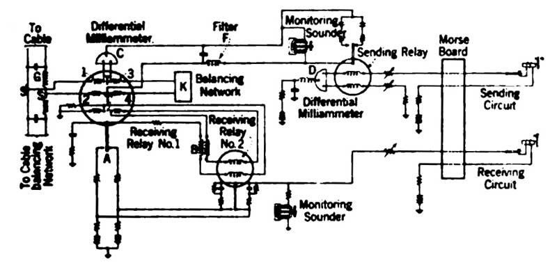
The outgoing high-frequency current passes through a two-stage amplifier, the last stage of which consists normally of one vacuum tube, either No. 7 or No. 8 in Fig. 19. By means of a switch at the carrier panel, the second tube may be connected in parallel with the first to increase the current. The output of the transmitter is controlled by the inter-stage potentiometer P. The current from the amplifier passes through a single tuned circuit TC in Fig. 19, which can be accurately tuned to the frequency of the outgoing current by means of the adjustable condenser C2. The frequency of this current is controlled by the adjustable condenser C1 in the oscillator circuit. At the other terminal of the cable the high-frequency alternating current passes through the bridge transformer and receiving filter. Since the attenuation of the cable for the carrier currents is high, the received current is passed through a multi-stage amplifier before it reaches the detector which rectifies it and causes it to operate a sensitive receiving relay. As shown in Fig. 19, the receiving relay retransmits the signals by means of direct current over the subscriber’s receiving loop. The receiving circuit differs from that used in land carrier telegraph systems in the following features: Instead of the usual double tuned circuit for selecting the proper frequency, a narrow-band, highly selective fixed filter is placed before the amplifier. The gain attainable in the receiving amplifier is much higher than is provided in land-line systems. When less than the full gain is required tube No. 1 can be cut out by means of a key. The sending and receiving carrier telegraph circuits work directly into subscribers' loops at Havana. In through-line traffic, which is the only type of telegraph traffic now required at Key West, the carrier circuits are arranged to operate standard land-line duplex telegraph sets. The d-c. telegraph circuits from the carrier apparatus pass through jacks in the morse boards for convenience in connecting them to any desired land lines or subscribers' loops. The arrangement of Fig. 19 is that used for full-duplex operation, that is, when it is desired to transmit messages simultaneously in both directions over the cable. By means of a switch on the carrier panel the circuit may be adapted to half-duplex operation. In this case, messages can be transmitted over the cable in both directions but not simultaneously. Direct-current Telegraph A direct-current telegraph unit is permanently connected at each end of each cable as a repeater of telegraph signals between the submarine cable and a land circuit. The four units at the right of Fig. 18 are the direct-current telegraph panels, one being a spare unit. A schematic diagram of the direct-current telegraph circuit arranged for repeating between the submarine cable and subscriber’s loops, is shown in Fig. 20. This figure shows the arrangement for full-duplex operation over the cable. In this telegraph circuit the separation of the sending and receiving branches is accomplished by the mainline receiving relay, which in its relation to these branches functions like a bridge transformer. Outgoing signals to the cable divide at the points T, half the current passing through coils 1 and 2, and the other half passing through coils 3 and 4. These coils are wound so that with a good balance between the balancing network and the circuits on the opposite side of the relay, the armature A is not actuated by the sending currents. It is evident, however, from Fig. 20 that incoming signals from the cable will produce an additive effect in passing through the relay coils and operate this relay. The network K balances, for the frequencies involved in direct-current telegraph operation, the impedance between the points S and S'. Reference to Figs. 10 and 20 shows that this includes the two halves of the filter G in parallel, the cable and the cable balancing network as well as the impedance at these frequencies of the telephone and carrier apparatus. The network contains a fixed portion to balance the filter G and an adjustable portion to balance the cable and the associated equipment just mentioned. The balance can be tested by observing the differential milliammeter C (Fig. 20) as signals are transmitted from the sending branch.
Signals coming from the subscriber’s sending loop operate the sending relay which acts as a pole-changer to reverse the polarity of the 10-volt battery applied to the cable, in conformity with these signals. The low-pass filters F and G transmit freely all frequencies below about 80 cycles but practically prevent the passage of higher frequencies. They thus allow free passage of those components of the sending currents which are necessary for the operation of this system, but suppress those which might cause interference in the telephone and carrier channels. A feature of the receiving branch is the tandem connection of receiving relays. Incoming signals from the cable actuate the sensitive receiving relay No. 1 and, as shown, in Fig. 20, the operation of this relay in turn actuates the receiving relay No. 2. The armature of receiving relay No. 2 acts as a pole-changer to transmit signals to the receiving loop. The larger energy available for the operation of this relay enables it to commutate successfully the comparatively heavy currents which are transmitted into the land line. The networks connected between the armature and the contacts of receiving relay No. 2 operate to suppress sparks at break. The purpose of the transformer B is to quicken the action of the receiving relays. The circuit as shown in Fig. 20 and described above is adapted to working into two loops for a local telegraph subscriber. Apparatus equivalent to a standard duplex set is provided in the telegraph panel so that by throwing a switch, the set may be adapted to duplex operation over a land line. This is the condition at Key West where all the telegraph circuits are continued northward. Switches are also provided in the panel for adapting the circuit to half duplex operation instead of full-duplex operation. The sending loops, the receiving loops and the 120volt batteries of the land sides of the direct-current telegraph units are connected through jacks in the standard Morse Boards so that they may be available for cross-connecting or testing. Auxiliary Equipment A jack panel and two testing panels in each terminal office provide means for testing the circuits and terminal apparatus and for changing their connections. The jack panel contains a system of jacks to which all circuits are connected and on which are terminated all important pieces of equipment such as amplifiers, filters, networks and bridge transformers. The testing panels contain an oscillator for supplying testing currents of telephone and carrier frequencies, transmission measuring apparatus for testing the telephone repeaters and circuits, apparatus for testing the balance of the networks and lines, thermocouples and meters for measuring the carrier currents, a frequency meter for testing their frequencies and apparatus for testing the efficiency of the carrier terminal sets. In Fig. 15 the jack unit is at the middle of the row of panels, with a testing unit on each side. A 24-volt storage battery furnishes current for the filament circuits of all the vacuum tubes in the telephone repeaters, carrier telegraph panels, ringer circuits and testing apparatus. Positive and negative 120volt batteries are provided for the standard duplex sets and for the local circuits of the carrier and direct-current telegraph sets. The positive 120-volt battery also furnishes plate current for all vacuum tubes. Grid potentials for the vacuum tubes are derived from a small capacity 60-volt storage battery. A number of 10-volt batteries are provided for the direct-current telegraph circuits over the cables. All batteries are charged from the local power mains through mercury arc rectifiers, with gas-engine-driven generators for charging in case the electric power supply fails. Battery circuits for supplying the terminal equipment pass through control apparatus mounted on the relay rack shown in Fig. 17. On the two sections at the left are rheostats for adjusting the filament currents of the vacuum tubes, with associated relays and resistances in these circuits, and also meters for measuring the filament and space currents and the voltages used. Another rack, not shown, carries the fuses and other protective equipment associated with the power supply. Operation The relation between the total transmission equivalent of the telephone channel over the cables, the available gains in the terminal amplifiers and the balance obtained between the cables and the balancing equipment was such that this channel could be operated at an efficiency materially higher than that required for connections terminating in Havana and Key West and also over a large range of current levels. As the cables were to be used in general as links in long circuits, the operating adjustments which were finally adopted were set rather by the circuits as a whole than by the cables. One of the cables was connected at Key West to a land line to form a direct New York-Havana circuit, a second cable to form a direct Jacksonville-Havana circuit and the third was arranged for a Key West-Havana circuit. The New York-Havana circuit was set to have a transmission equivalent of 12 miles of standard cable. As the New York-Key West section has an equivalent of 10 miles, the net equivalent of the cable and terminal apparatus is only two miles. The Jacksonville-Havana circuit was set at 11 miles and the Key West-Havana at 10 miles. Switching through New York, operating equivalents are obtained for Havana-Chicago connections of approximately 16 miles and for Havana-San Francisco [17] of 20 miles. In addition to the submarine cables, the Havana-Chicago circuit contains 2453 miles (3940 km.) of land line and the Havana-San Francisco 4790 miles (7700 km.)
With these equivalents, satisfactory commercial connections can be established not only from Havana to points on the eastern part of the United States, but also to the Pacific coast. The application of repeaters to the Cuban toll lines makes it possible to establish commercial connections from points along the island to points in the United States. While the majority of the telephone connections over the cables have been for calls between New York and Havana, commercial calls have been handled satisfactorily to points all over the United States, such as Boston, Washington, Chicago, St. Louis, San Francisco, New Orleans and Atlanta, also to Toronto and Montreal in Canada, and to points in Cuba such as Matanzas, Sagua, and Santiago. The traffic between New York and Havana has been so large at times as to require two of the cables to be used in direct New York-Havana circuits. The d-c. telegraph channels operate so well that their connection to land-line telegraph circuits from Key West to New York does not appreciably affect the maximum speed of the circuit. The carrier-current telegraph channels are good enough for the operation of four channel multiplex printers if it should be desired to use them for such service. In planning this cable system it was intended that a demand for more telegraph facilities would be met by increasing the number of carrier channels per cable. As has been noted, the initial apparatus and land connections provided for the commercial operation of only six telegraph channels, one d-c. and one carrier channel per cable, on the basis that this number would meet the initial service requirements. In order, however, to obtain information regarding the operation of additional carrier channels and to provide spare telegraph facilities in case of cable failures, a fifth carrier telegraph set was provided at each terminal, together with special receiving selective circuits. With this apparatus three carrier telegraph channels were successfully operated over one cable, using frequencies up to 4200 cycles, for which the equivalent of the circuit between the terminal offices is 48 miles. It is possible that this number of channels can be further increased. The present arrangement of the carrier telegraph apparatus makes it possible, therefore, to carry six telegraph channels over two cables or four over one cable. This will prove very useful in maintaining service in case of cable failures. At the time of the opening of service over these cables under the auspices of the Pan American Union, greetings were exchanged between the President and other officials of the United States at Washington and the President and officials of the Cuban government at Havana. In connection with this demonstration, the circuit was extended through New York and San Francisco to the Island of Santa Catalina, off the coast of California, in the Pacific Ocean. As this island is connected to the mainland by radio telephone [18], this connection, 5470 miles (8800 km.) in length, involves the radio connection through the air, a 5322-mile land line across the United States and the submarine cable from Key West to Havana. This circuit containing twenty-five telephone repeaters illustrates the possibilities of the present state of development of telephony.
The work described in this paper involved the application of ideas from practically all branches of the telephone and telegraph fields and from a number of organizations. The Western Electric Company was retained by the Cuban-American Telephone and Telegraph Company as engineers and purchasing agents for the cables and to manufacture and install the terminal apparatus. The Cuban Telephone Company retained as consulting engineer Sir William Slingo, who also assisted the Western Electric Company in the inspection of the cable during the manufacture and laying. The electrical design of the cables, the method of operation, the design and arrangement of the terminal apparatus and the adjustment of the system for operation were the work of the engineers of the American Telephone and Telegraph Company and the Western Electric Company. The Telegraph Construction and Maintenance Company, Limited, of London, which manufactured and laid the cables, was largely responsible for the mechanical features of the cables, such as the design of the armoring for the different depths of water involved and the arrangement of the copper tapes. The recommendations of the engineering firm Clark, Forde and Taylor, retained by the Western Electric Company, were obtained on many of these matters including the routes to be followed. Discussion Bancroft Gherardi: The two questions that required much care and thought in the design of this cable were, first—shall the cable be continuously-loaded or coil-loaded, and, second, shall it be a single or a multi-conductor construction? There were serious questions involved in each. In the first place, as to the loading. Coil-loading is in many respects more efficient than continuous-loading, because with coil loading, you can get practically any inductance per mile that you desire, and so you can, within very considerable limits, increase the efficiency of the circuit. With continuous-loading, however, there are very sharp limitations on the possible inductance per mile that can be attained with any practical construction. As we saw the problem at that time, and as we still see it, the coil-loading would have been chosen, for electrical reasons, but it presented most formidable mechanical difficulties. In the first place, the making of a cable of that kind, interrupted periodically by coil cases and coils, and laying it in deep water was a very formidable matter. In the next place, the maintenance of the cable would necessarily be complicated by having points of discontinuity. The attachment of the cables to the coil cases and the coil cases themselves would necessarily be elements of weakness. This weakness is not serious in a land cable, as trouble, if it occurs in a land cable, can be cleared in a few hours. On the other hand, if trouble develops in a cable of the kind in question, it may be weeks and under bad weather conditions and unfavorable location of cable ships, it might be months before the trouble could be cleared. The coils were, therefore, excluded for mechanical reasons. The other question was the one of the single-conductor versus the multi-conductor cable, and this brought up a related question that of one cable versus several cables. These questions, as you see, are tied right up with each other. The single-conductor cable necessarily meant grounded-circuit operation. In the case of the metallic circuit cable, the obvious method of operation would be to build probably a cable of four wires and undertake to operate two physical metallic circuits, and possibly a phantom circuit, with a more remote possibility of getting a fourth circuit, that is, a grounded phantom circuit from the combination. The choice finally was determined by the consideration that we could not afford to put all of our eggs in one basket, as we might lose the whole cable at one time. Therefore the alternative of three separate cables was chosen, although it required a great deal of study and investigation as to the general question of the grounded circuit operation of cables of that character, and their operation under the particular conditions existing between Key West and Havana.. Our investigation satisfied us that we could safely count on that method of operation. These investigations were very extensive and very carefully made. We satisfied ourselves that the cable itself, and the service from it with any degree of amplification we would wish to place on it, would be satisfactory. William McClellan: What effect is long distance wireless communication going to have on long distance telephone? At present there is a certain lack of secrecy which our customary long distance lines give in part at least. Bancroft Gherardi: I will be glad to say a word in answer to the question which has been asked. The matter of utilizing wireless in that connection was very carefully considered at the time the cables were being considered and it has been reconsidered recently in this form—if we were to do the job again, would we do it by means of wire or wireless? In each case the answer has been the same. Most of the communication has been on business, matters—particularly last spring, and to a certain extent this fall, there were a number of very serious financial failures avoided by the use of the cables. These were matters which required prompt communication with a considerable number of different institutions, and if action was not taken in twenty-four hours there would be a financial failure, and there was a situation in Cuba in which a few failures might start things going and create a very much more serious state of affairs than the one which actually existed. Obviously, wireless communication, certainly in the present state of the art, would have been entirely unsuited for such service. The mere mention of such topics in the air, the broadcasting of such questions as were discussed in these communications would create the effect which it was desired to avoid. But excluding altogether the matter of secrecy, and excluding altogether the matter of interference, atmospheric or otherwise, we have thus far been unable to figure out how we could give an equally extensive and dependable service and give it as cheaply by means of radio across that distance, as we can by means of the cables. See the 1920 Brazil - Uruguay - Argentina telegraph cable, also made by Telcon, for photographs of this type of cable. See this explanation of sea earths from DE GIULI, Italo, Submarine Telegraphy - A Practical Manual, London, 1932, Sir Isaac Pitman & Sons, Ltd. Thanks to Tom Perera for the 1921 cable sample shown near the top of the page. This image, and “Telephoning to Cuba” were not part of the original paper. The second image of Fig. 3, numbered Fig. 41, is from Louis Casper’s book, Telephone and Telegraph Cables, Scranton, 1928, International Textbook Company. For further information on the history of the Key West - Havana telephone cables laid between 1921 and 1950 see this article by J. Gregory Griffin. |
|
Last revised: 18 May, 2023 |
|