History of the Atlantic Cable & Undersea Communications
from the first submarine cable of 1850 to the worldwide fiber optic network
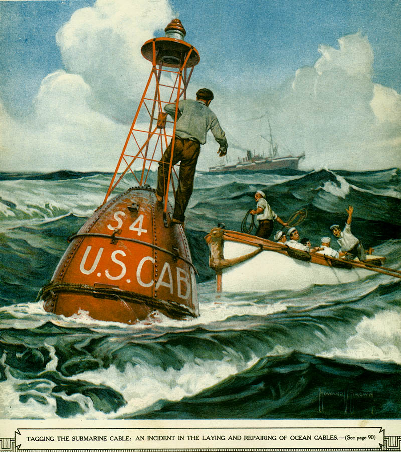
Laying the Cable - 1922
|
History of the Atlantic Cable & Undersea Communications |
|
Laying the Cable - 1922 |
|
|
From Scientific American, August 1922 Submarine
Telegraph Cables by Lt.-Col. C. deF. Chandler, U.S. Army, Ret. |
|
|
|
THE aerial wire lines for the ordinary land telegraph circuits are so much in evidence that the methods of construction and operation are quite well known. But with few exceptions information regarding submarine telegraph cables is confined to persons associated in some way with that industry. Therefore a brief description of the cable itself and manner of laying and repairing it should be of general interest. The electrical conductor which forms the center of the cable usually consists of a strand of seven copper wires (occasionally 11 or 19), over which is an insulation of gutta-percha or indiarubber. A stranded wire conductor is better than one solid wire of equal conductivity, because flexibility is essential during the laying and repairing operations. This cylindrically insulated conductor is known as the cable core. The quantity of copper for the conductor and of rubber for the insulation is usually expressed in pounds per nautical mile. By way of examples, one trans-Atlantic cable has 700 pounds of copper and 360 pounds of gutta-percha per mile for a length of 2054 nautical miles. These amounts allowed an ordinary working speed of 185 letters per minute, which has been increased by magnifiers about 40 per cent. Another somewhat earlier Atlantic cable has 650 of copper and 400 of gutta, allowing a normal working speed of 240 letters per minute. This latter cable is 1853 nautical miles, and the magnifiers similarly increase the working speed 40 per cent. These rates are in both directions, as the cables are duplexed. Some short cables have only 107 pounds of copper and 177 of insulation per mile. The Atlantic cable, with the 700 pounds of copper for the conductor, has a resistance of 1.69 ohms per nautical mile. Some of the smaller cables have as much as 21 ohms per nautical mile. The electrostatic capacity is not so variable; ordinarily it is between .3 and .5 microfarads per nautical mile. Cable core in poor condition has much less capacity. The measurement of insulation resistance or dielectric resistance is also referred to as the electrification of the cable. The results are not constant;: that is, the electrification after five minutes' application of the testing current is often quite a different reading than after one minute. The result is usually stated in megohms per nautical mile after one, two or five minutes' electrification. New gutta cable core should show at least 500 megohms per nautical mile. Indiarubber core has shown 1230 megs before laying and 2500 megs after laying. The best section of the Alaskan cable system (rubber insulation) measured 3800 megs per mile after laying. All of the electrical measurements are affected by temperature changes and the capacity and insulation resistance are changed as well by the tons of pressure produced by great depths of water. By increasing
the thickness of the insulation between the conductor and the sea water
which completes the electrical circuit, the electrostatic capacity is
reduced, and by increasing the quantity of copper the electrical resistance
is lowered, both of which permit of faster operation. The longer a cable,
the greater the electrostatic capacity and resistance, consequently it
is customary to design each cable for the particular place where it is
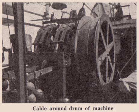
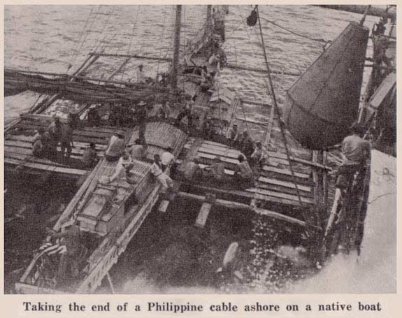
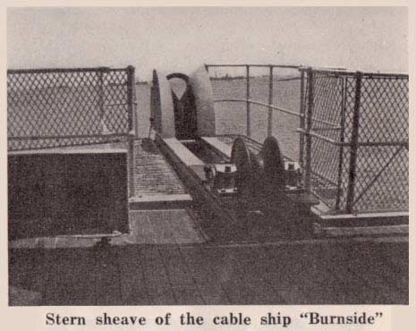
to be laid, having reference to the length and speed of signaling desired. To protect the core from damage and give it mechanical strength for laying and repairing, there is a covering of mild steel armor-wires laid helically and separated from the core by a cushion of jute. Outside the armor-wires there are two windings of jute to prevent the armor-wires from spreading apart or "bird-caging," as it is called. This outer jute is well tarred and finally covered with powdered soapstone to lessen stickiness of the tar in warm climates. The smallest-sized cable is laid in the deepest water because the chances for mechanical injury are slight and armor is needed only to give the cable strength for laying and repairing. For moderate depths of water there is an "intermediate" type of cable which is similar to the "deep sea" except that the armor-wires are larger. At landings and near shore where tidal currents and wave action tend to move the cable, particularly over rocky or coral bottom, an additional layer of much heavier steel wires is provided; this double armored type is known as "shore end" or "rock" cable. The double armored types have the tarred jute and soapstone only over the outer layer of wires. Ordinarily the core is of the same size for the entire length of any one cable, including the heavy end sections. The outside diameter of cable varies from four-fifths of an inch for small deep-sea type up to 2½ inches for shore end. The weight of complete cable may serve better to indicate the type differences. Deep-sea weighs from 1½ to 3½ tons per nautical mile; intermediate from 3½ to 12½ tons; armored shore-end from 11 to 19 1/2 tons per nautical mile. It should be apparent that submarine telegraph cables, in mechanical construction, are very different from the lead-covered telephone cables containing several hundred pairs of conductors, which are so familiar in every American city and town. All of the trans-Atlantic and Pacific cables and in fact nearly all of the submarine telegraph cables of the world employ gutta-percha as the insulating medium. The supply of this substance is limited and seems to be controlled by British and French interests. Indiarubber is used very extensively throughout the world for a great variety of purposes and an ample supply seems to be always available. Because of the assured supply of indiarubber and lack of experience of American manufacturers with gutta-percha, and the need for developing the cable manufacturing industry in the United States, all cables which hare been made for the Signal Corps of the Army and laid in the Philippine Islands and to Alaska have had indiarubber as the insulating material. Considering reliability and durability, gutta-percha has proved to be superior, but time and cost were the factors which determined the adoption of indiarubber for the military cables, which had to be provided as quickly as possible. However, the experience which has been acquired by American manufacturers now assures rubber cables of much better quality. Heating only slightly above ordinary temperatures is sufficient to make gutta-percha soft so that it can be drawn through a die over the conductor and easily worked by a hot iron in making joints. After being molded into the shape desired, indiarubber must be vulcanized with sulfur and other ingredients to insure permanence. When that is done, exposure to dry air or increased temperature have no deleterious effect as is the case with gutta, which must be immersed in water promptly after manufacture and constantly maintained thus. It would have been impossible to transport gutta-core cable in the dry holds of merchant vessels to and through the tropics, as was done with rubber-core cable needed at Manila. The cable required for the Alaskan system was made near New York and shipped around Cape Horn to Seattle. The most efficient type of cableship is one designed for the purpose, but it is possible to convert certain merchant vessels when either time or money is limited. The primary requisite of a cable-laying steamship is to have several large circular tanks in the spaces ordinarily occupied by cargo holds; in these the cable is coiled and covered with water. A cableship ought to have ballast tanks of greater capacity than a cargo ship. A clipper bow is advantageous. On the bow are installed two or three large sheaves, over which the cable passes, and grapnel rope during repair operations. An essential feature of the equipment for cable repairs is a special form of powerful hoisting machine, usually having two drums of approximately six feet in diameter, around which the cable or rope is passed several times and is controlled in that way. The cable machinery is located according to the conformation of the vessel. On the "Burnside" it is on the main deck forward.
On the main deck there is a deep-sea sounding machine, and slung to the mast stays or lashed on deck there are a number of buoys of various sizes corresponding to ocean depths. Below decks will be found grapnel rope coiled in small tanks; quantities of iron sounding-shots, mushroom anchors needed to hold buoys in place, chains in assorted sizes, grapnel hooks of different kinds, spare parts, splicing material and plenty of rope. To facilitate the landing of cable from ship to shore, the "Burnside" carried two steam launches and two cable cutters; these latter are small boats, but of wider beam and stronger construction than ordinary lifeboats. On the forecastle deck there are two dynamometers in line between the cable drums and the bow sheaves; these indicate the tension on cable or rope passing under them. Over the center of each tank is a bell-mouth and at various points over the decks are bell-mouths and rollers for guiding the moving cable in the desired direction. There is also a payout machine on the after main deck, for use in cable-laying operations only. Deep-sea soundings are made by a special machine, perfected by Admiral Sigsbee and bearing his name. It consists of a small steam engine geared to a drum on which is wound a piano wire several miles in length without a splice. The wire in passing out operates a dial indicating the depth of water. On the lower end of the wire is attached a small brass tube having a hook for supporting a spherical iron weight, which has a hole through its diameter for the purpose of receiving the brass tube referred to. The heavy weight is very necessary in order to take the wire down to the bottom rapidly; otherwise ocean currents or drifting of the ship would allow the measuring wire to pay out at greater length than the true vertical distance to the bottom. As this tube strikes the ocean bed, the trip-hook releases the iron weight and at the same time the lower end of the tube picks up a sample of the mud or sand comprising the bottom. The loss of the iron weight permits the sounding wire to be pulled in rapidly without undue strain on it.
The floor of the ocean is surveyed first by soundings so that a route may be selected which will avoid laying the cable on the edge of a ledge, across a deep spot of small area, or over a submarine mountain. The cable is carefully coiled by hand in the tanks in flakes (flat layers) from the wall of the tank inward near the center cone. This facilitates the paying out at from 6 to 8 miles per hour. While the cable is passing out of the tank, it occasionally becomes tangled due to stickiness of the outer tar covering during warm weather. To meet such an emergency, an alarm bell is located on the navigating bridge with a contact button held by a petty officer who is constantly observing conditions in the tank. In case of a tangle, the ship's engines are reversed and usually in time to prevent the cable from parting. For laying more than a short piece of cable, as in repair operations, it passes out over the stern. The cable is controlled by several turns of it being around the large drum of the pay-out machine which is well provided with powerful water-cooled brakes; these are adjustable so that the amount of tension may be regulated to correspond with the depth of water, the speed of the ship and the amount of slack desired. Between the pay-out machine and the stern sheave there is another dynamometer which at all times indicates the tension on the cable. The pay-out machine is equipped with a revolution counter which serves as an exact measure of the length of cable which has passed out. While laying is in progress, the position of the ship is frequently determined and plotted by the navigating officers. The testing instruments remain connected to the cable so that in case the strain should produce a fault, it would be detected promptly.
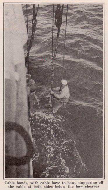
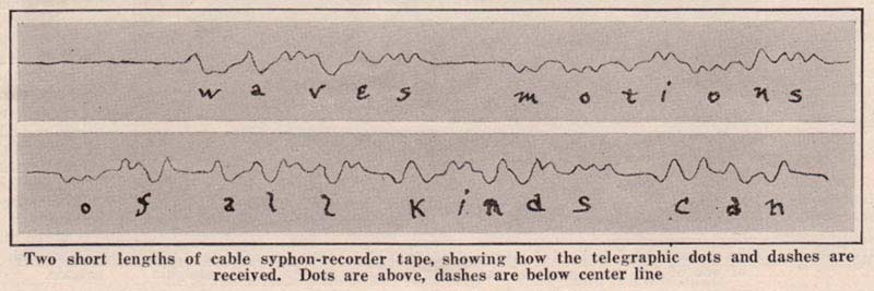
The location of a fault in a cable involves only careful and accurate electrical measurements, but even to the most experienced cable electrician, certain kinds of faults present difficulties in accurate location. Knowing the electrical resistance per mile of the conductor, if there is a complete break with the copper exposed to the sea water, the measurement of the total resistance represents the number of miles to that fault. However, at times, only the conductor breaks inside the insulation so that an electrical circuit is not completed, in which case the electrostatic capacity and insulation-resistance measurements indicate the length of cable to the fault. It is the slight leakages of current which require more complicated and experienced testing, ordinarily from both ends of the faulty cable and with positive and negative polarities. Then applying a little algebra to the readings from both ends, the distance to the fault is determined remarkably close. The cableship reaches the approximate position of a fault either by the usual astronomical observations or by dead reckoning when the sky is obscured. When sufficiently near shore, the ship's position is determined by angular bearings on prominent landmarks. The first action is to take a sounding as it is essential to know the depth of water; then a buoy is anchored on the assumed location of the cable, as a guide in the grappling operation. The type of grapnel hook used depends upon the depth of water and nature of the sea bottom. There are various shapes to suit different conditions such as mud or rocky bottom. The rock grapnel has prongs which are capable of moving against a spring, and thereby release themselves if the end catches on a rock. Another special type is designed to cut the cable when caught, holding fast to one end and freeing the other. That is imperative for cables laid in very deep water, as it would not be possible to raise the cable to the surface intact without causing great tension, which probably would result in breaking it before reaching the surface. The grapnel of kind chosen is at the lower end of a flexible stranded steel rope made in sections which are shackled together. The length used is at least 40 per cent greater than the vertical depth of water so that the hook will be sure to drag along the bottom as the ship moves forward slowly, back and forth across the route of the cable. By steadily increasing its reading the dynamometer under which the grapnel rope passes indicates that the cable is caught by the prongs of the grapnel. Rocky bottom causes sudden variations in the dynamometer indications. When there is plenty of slack or from depths of only a few hundred fathoms, the cable is drawn up above the surface; two other grapnel ropes are attached to the cable by stoppers on each side of the hook; next the cable is cut by a hacksaw between the stoppers. Then by heaving in on one rope and paying out on the other, each end of the cable may in turn be brought on board for electrical tests. The direction which proves to be good is then paid out again with a buoy attached to the upper end. The machinery then draws in the other cable which contains the fault. By leaving certain testing instruments connected while heaving in, it frequently happens that, as the fault comes above the surface, or as the cable is bent in passing over the bow sheaves, the sudden change in the electrical characteristics indicates that the fault is on board even if the tests did not locate the position accurately. The cable is now cut and tested shoreward; if clear of the fault, a splice is made to a new piece of cable which is then laid out to the buoyed end which first tested faultless. A second splice is then made; the bight is dropped overboard and the repair job is finished. In deep water the procedure is similar except that it is necessary to pick up the cable twice by grappling because the first time cuts and holds only one end. An indiarubber joint is made by vulcanization with heat supplied either electrically or by boiling in paraffin, after which the jute and armor wires must be carefully laid on and then a seizing of spun-yarn over the entire length of five or six feet. At least one hour is required. A gutta-percha joint can he made more rapidly and easily by manipulating a hot iron, but the armor wire procedure is the same for both kinds of cable. The conductor of the cable is separated from the sea water which completes the electrical circuit by only a small fraction of an inch. Therefore the electrostatic capacity of the cable is much greater than for the circuits of aerial land wires. The land lines are usually divided into separate short lengths by automatic repeaters every 500 miles or less, which is not practicable for cables. Consequently there is a lag or electrical drag in cable signaling which prevents the use of the sound reading instruments as universally employed in the United States for telegraph service. The retardation in long submarine cables is so great that the complete interruption followed by the flow of current in making signals at the sending end is not apparent as such at the receiving end. The cable acts as an electric condenser which is charged positively or negatively in combinations which form the telegraph code and at the receiving end can be read on recorder tape. An ordinary telegraph relay would not respond to the extremely small amount of current which filters out at the far end of the condenser, perhaps three thousand miles away. The first receiving instruments employed on cables were very sensitive galvanometers which slightly moved a small mirror about half an inch in diameter attached to the moving coil, thereby reflecting a beam of light to the right : and left representing the code. Even now the mirror galvanometers are useful for receiving messages on cableships. The modern receiving instrument is called a siphon-recorder because there is a delicate siphon of glass through which ink is spurted in tiny drops on to a moving strip of paper by means of an electrical vibrating device. In this way the glass siphon is free to swing according to the positive and negative impulses received, without the end rubbing against the paper. A wavy line on a paper tape is then the means for reading the messages over long submarine cables.
Practically all cables in good condition are duplexed; that is, two messages are sent, one from each end, at the same time. To do this, very careful electrical adjustments, called balancing, must be maintained at all times. Quadruplexing of long submarine cables has not been satisfactory. Radio communication is subject to interruption by atmospheric electrical storms and interference by other stations using the same wave lengths. Furthermore, all messages transmitted by radio can be read by all other stations. It is considerable trouble to code and decode all commercial messages. Commercial radio stations have been in operation for many years without noticeably taking business away from the cables and in fact new cables are being laid and projected; therefore it seems reasonable to expect that both systems will continue to be used, just as the telephone supplements, but does not replace, telegraph communication. The submarine telegraph cables of the world number 530, with a total mileage of about 242,195; a sufficient length to encircle the earth at the equator about ten times. The longest section of submarine cable is part of the British Pacific cable between Vancouver and Fanning Island. This very long section has the remarkable record of uninterrupted service from natural causes since the original laying 19 years ago; except that during the recent war, the German cruiser "Nurnberg" cut this cable as an act of hostility. |
Copyright © 2007 FTL Design
Last revised: 30 November, 2008
Return to Atlantic Cable main page
Research Material Needed The Atlantic Cable website is non-commercial, and its mission is to make available on line as much information as possible. You can help - if you have cable material, old or new, please contact me. Cable samples, instruments, documents, brochures, souvenir books, photographs, family stories, all are valuable to researchers and historians. If you have any cable-related items that you could photograph, copy, scan, loan, or sell, please email me: [email protected] —Bill Burns, publisher and webmaster: Atlantic-Cable.com |