History of the Atlantic Cable & Undersea Communications
from the first submarine cable of 1850 to the worldwide fiber optic network
Early Telegraph Cables -
Precursors of the Submarine Cable
|
History of the Atlantic Cable & Undersea Communications |
Early Telegraph Cables - |
|
Some Specimens of Early Telegraph
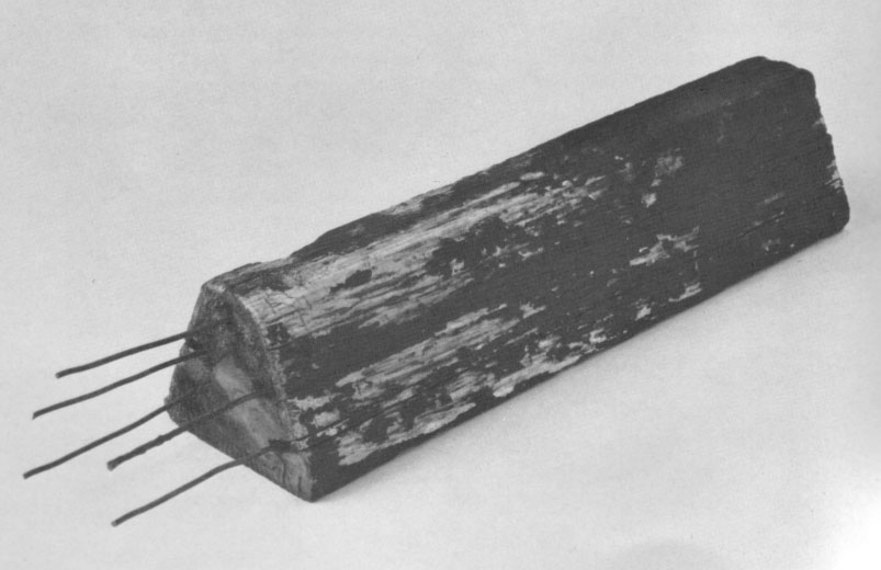
Cables Francis Celoria Summary Introduction These wires, as well dated as can be possible in such contexts, are also raw material for historians of metallurgy. With modern techniques one could learn about purity of metals (impurities can increase resistance) or about the kind of drawplates used in producing them (note 3). Perhaps scanning electron microscopy might see surface features on a wire that might not be suspected in a superficial examination. Such dated wires could also form a repository of information about the ageing of materials. But museums have a trusteeship function that must preclude unsystematic "poking about" analogous to the investigatory scrapings, probably done with a jack-knife, that were inflicted on the wood spar of "fossil telegraph" of 1837. Fortunately there still exist several metres of copper wire from these spars from which a few millimetres might one day be cut to ascertain, for example, conductivity. Since the diameter seems to be variable (a range of" 1.50 to 1.72mm), the setting up of such an investigation will require meticulous and elaborate experimentation. Many of the cables described below may genuinely be regarded as archaeological since they have been dug out of the ground. Unfortunately they have turned up by chance rather than as a result of systematic excavation. It is quite possible that many archaeologists have come across buried cables over a century old which have been ignored as modern. By 1908 a Post Office engineer, G.H. Comport, would be found mentioning the finding of the troughing of what was probably the old Birmingham-Manchester cable, between Walsall and Stafford. He noted a cable of 1852 dug up in Glasgow and others at Larkhall (Lanarkshire), and, at Portpatrick, traces of the London-Belfast cable of 1868.(note 4). In 1959 was found at Tamworth, Staffs, a 2-inch cast-iron pipe of about 1890 containing 36 wires and a core (note 5). A few years earlier, in 1954, was recovered during development schemes in Gloucester the conduit and cable illustrated in Fig. 7. Such considerations make it necessary to put the main emphasis in this article on systematic descriptions of finds so that comparisons can be made and of find-places. The five wires fixed in the Euston-Camden Town spar were arranged in a distinctive way, as the illustration shows (Fig. 1). One cannot at the present stage of research suggest why they were so placed. Was it to cope with underground conditions or were naive ideas about insulation, or even induction, in operation? It should be recalled that most of the investigations suggested above relate to copper wire. But other metals could be involved such as the iron and brass of some of the other wires as well as the zinc that w as used for galvanizing them. The lead of some of the sheaths may possibly yield something for the history of metallurgy as also might the cast-iron conduits. The organic components of these early cables also offer considerable opportunities for research, not merely about the origins of the material but about details of "biodeterioration" of well-dated materials. Examples of such might include the sandy tar over the Euston-Camden Town spars, the "pitch" or "tar" in the 1844 London cable and the gutta-percha of the 1849 cable and, possibly, various fibres such as cotton that might be hidden under the tar. It is hoped that the above remarks might lead to the devising of investigations of these cables to be carried out on an interdisciplinary basis and within standards satisfactory to the Science Museum. Some of the cables described below are "unique" not because of rarity but because they are ideal examples of "historical archaeology" in its post-medieval aspects. These specimens can be documented in great detail, which is not that common. Thus we not only can examine the Euston-Camden Town telegraph, but we can read the correspondence of William Fothergill Cooke where he describes the problems he had to solve concerning these spars and their wires and, as well, we can read the bill set by the Cubitts (note 6) for the operation which is detailed down to the least item of expenditure. Furthermore Cooke" s patent specification of that year also describes the spar in considerable detail. (No. 7390 of 12 June 1837). Similar comments can be made about the Indian underground cable of 1850-1. The Euston-Camden Town wires, 1837 (A) Inventory number 1968-658; a wood spar, with five embedded wires, about 780mm (or about 30 in.) long presented by Messrs Preece, Cardew & Rider of 8, 10 and 12 Queen Anne's Gate, London. The wires are held in their slots by strips or "tongues" of wood. This spar presents a battered appearance and shows traces of investigatory scraping. It also differs from the other specimen in retaining on it a quantity of the sandy tar that had been used to cover it. Underneath are some nail or screw holes about 300mm or a foot apart. These holes may well have been the result of mounting for an exhibition in the past.
The "deal tongues" to hold the wires in are approximately 3 x 2.5mm in section. The five copper wires, which protrude from one end, are slightly bent or kinked at several points, and further, they are covered with patches of tar so that measurements at regular intervals are not possible. The following readings were however taken in millimeters at as regular an interval as could be managed:
The mean of the above is 1.6 mm or 0.063 of an inch or 63 mils, to use the terminology adopted by the first electricians. This is within the range (62 to 70 mils) of early Victorian wires of No. 16 gauge (note 7).
The system, it should be said, was not regarded as highly successful - though it worked. Perhaps a five-wire system was not necessary for a signal to the engine-man. Ultimately Robert Stephenson used a pneumatic whistle signal. There is still some uncertainty about the instruments used. We know that in July 1837 a four-needle demonstration instrument was made, though this has not apparently survived. In August of that year an improved version with five needles was paid for by Stephenson and later sold back. The adaptations that were made in instruments at the time make it difficult to explain the precise function of the five wires of the Euston-Camden Town conduit (note 8). W. F. Cooke's wires in quill insulators:
1842-5
One (Inventory No. 1884-184A, Fig. 2) of the two wires in quills is of unrusted iron and coated with a grey metallic salt which is assumed to be what is left of the zinc of galvanization. Since we know that Cooke had painted or tarred wires at first, 1842 is too early a date. However, The Great Exhibition Catalogue (note 12) of 1851 mentions that galvanizing had been introduced by a Frenchman called Sorel some eight years earlier, that is 1843. Cooke enthusiastically adopted galvanization, becoming a director of the Galvanized Iron Company (note 13). It is possible that Cooke did not first use galvanized iron wires on the Great Western, for one account (note 14) says that he first used it in Ireland for the telegraph of the Dalkey and Kingstown Atmospheric Railway in 1843. We may accordingly suggest that the wire is of the period 1843-5, the year 1845 being the one in which Cooke's ceramic "barrel" insulators were introduced (note 15). The iron wire on the post is so firmly fixed that it could not be easily examined. Its diameter appears to be about 3.5mm or 0.12 of an inch (120 mils); this would make it about No. 11 or 12 gauge. It is uncertain how far galvanization would have made a difference to the original gauge size.
The three-strand copper wire (Inventory No. 1884-184B, Fig. 3), held in another quill on the same post, is even more difficult to measure without disturbing it. Each of the strands is about 2.25mm or about 0.09 in. in diameter. This might be taken to be No. 13 gauge. The diameter of the stranded wire is about 5mm. Its date is harder to discuss and, making the assumption that it is earlier than the iron wire, and that it was used for overhead wiring started in 1842, one may suggest that its date is about 1842-3.
London's first underground
cable 1844 The piece, neatly cut at both ends, consists of a lead sheath 2mm thick and about 12mm in external diameter (see Fig. 4). This contains nine copper wires embedded in what appears to be pitch or tar. There is no say of telling whether the wires are bare or covered with some fibre like cotton. At one end the black material appears to have shrunk. This makes it very difficult to measure the diameter of the wires. While there does not appear to be any cutting of the wires on the slant, it is difficult not to have the impression that four of the wires are slightly wider in diameter than the other five, the four "larger" wires would appear to be ranged between 2.0 and 2.16mm (0.83 in. or 83 mils) in diameter, while the five 'smaller" wires appear to be about 1.6mm in diameter (about 0.63 in. or 63 mils). The outside of the lead sheath has a lightly striated surface that appears to be the result of hard brushing or sandpapering after recovery. The first gutta-percha cable, London 1849
There are embedded in it three iron wires with a mean diameter of 1.84mm (about 0.072 in. or 72 mils) set in a triangle that keeps them at a distance of about 3.5mm apart. For some confirmation of its background and dating we can accept Cromwell Fleetwood Varley's statement made in 1860 that "Gutta-percha covered wire was first used in the streets of London in 1849". But it is possible that the date of the first gutta-percha-covered cable can be put back to 1848, at least in an experimental form. At a conversazione of the Society of Telegraph Engineers held on 18 December 1876, Charles V. Walker, the president, exhibited "Thirty-six insulators, beginning with the first" of about 1845 onwards as well as 1848. Ap. 27 . . . The first piece of Wire (No. 8) covered in England with Gutta Percha . . . Band of six G. P. wires, as first manufactured in England . . . 1849 . . . the original Gutta Percha jointing Tongs. Walker was a meticulous recorder of dates as his other contributions to functions of that Society show (note 16). This cable was probably that laid by the Electric Telegraph Company between its Lothbury headquarters and Shoreditch (presumably the railway station). There was a subsequent line to Euston and King's Cross (note 17). An "immense improvement was noticed with such cables which were said to consist of three iron wires of No. 16 gauge in a gutta-percha cylinder of about half-an-inch in diameter. The iron wires, unlike copper, did not uncoil well and "would almost invariably knuckle out through the gutta-percha". Subsequently a single wire per "rod of gutta-percha seam" was used. but the cables were soon to fail because of "the gutta-percha seam opening longitudinally and exposing the conductor" (note 18).
A Midlands gutta-percha
cable of 1856 The gutta-percha insulation is a glossy brown, perhaps because of varnish, and in very good condition. Gutta-percha is vulnerable to oxidation and generally only "flourished" in underwater conditions. This cable may well have been hermetically wrapped in impregnated fibres and placed in a trough. Each copper wire is about 1.67mm diameter (range about 1.50 to 1.78mm) or about 0.066 of an inch, being 66 mils in the terminology used by the telegraph engineers of those days. A diameter of 66 mils puts it inside the range of 61 to 70 mils for No. 16 gauge wires of the period. Each copper wire is covered with gutta to produce a diameter of about 5.6mm. As exhibited in the museum the wires are lashed with thread into a prismatic bundle. It is uncertain whether or not the thread was put on after recovery.
A split-pipe conduit of the 1860s The cast-iron conduit (Fig. 7) presented to the Science Museum (Inventory No. 1970-492) by the Post Office was made by the United Kingdom Telegraph Company. It is labelled as being of 1863 and was excavated in Gloucester in 1959. It contains 12 gutta-percha-covered wires. These copper wires are about 1.70mm in diameter, or 0.067 in., which is inside the range for No. 16 gauge wire in that period. It is noted on the display label that the wire was rated at 40 lb per mile. They are covered with gutta-percha (much crumbled) to produce a diameter of about 4.60mm (mean of 4.46, 4.78, 4.50) or about 0.18 in. This wire bundle is on the whole not unlike the Midlands example above which has, apparently, a slightly thicker coating of gutta- percha on the wires. The cast-iron conduit for these wires was made with upper and lower portions that interlock. The maximum external diameter is about 62mm or 2.45 in.). There is in the museum another portion, 141mm long. of the upper section of a similar cast-iron conduit which is slightly larger (84.7mm or 3.14 in. in diameter) and might seem to be of similar origin (Fig. 8). But its inventory number, 1923-249, is however that of a specimen of ceramic half-pipes used for underground telegraphy in India in 1851 so that there is some doubt about its provenance. One can only guess that it is a British specimen that arrived in the same package as the material from India. The cable in Fig. 7 was recovered after cable markers were discovered in St Mary's Street during redevelopment. The pipe was found near a marker at a depth of 14 inches. The line ran from an office in Commercial Road, turning north-east to go along Upper Quay Street and St Mary's Square toward another office near the junction of Priory Road and St Oswald's Road. The pipes were said to be in 6-foot lengths joined by couplings. Raised lettering on the pipes were read as "U.K.T. Co Ltd - Henleys Patented" (note 19). The United Kingdom Electric Telegraphy Company was inaugurated in 1860 to establish a shilling rate for lines between London and the provinces (note 20). The original parliamentary act went back to 1851 (note 21) but opposition and competition created so many delays that some lines were not to be completed till l863-4. The U.K.E.T. Company was taken over by the Post Office in 1870 so that the pipe has a maximum date range of 1863-70. The article (note 22) which was used as a source for this information seems from local knowledge to be able to suggest reasonably that the date is 1863-7. The wires were said to be each rated at 40 lb per mile. The wire bundle was said to have been wrapped with hessian "impregnated with pitch, or something of a similar nature" (note 23). The only uncertainty regarding the pipe is that in the source consulted the external diameter is said to be 1½ inches. Perhaps this should have been the internal diameter. "Split-pipes" were descendants of the integral three-inch cast-iron gas pipes, such as were first used in London around 1844-5 for the Strand to Nine Elms stretch of the line to Gosport (note 24). It was troublesome to thread cables through pipes and half-pipes saved much time. The lower halves in the trenches could have the wires swiftly put into them and the upper halves could then be quickly put on and fixed. In 1852 W. Reid and T.W.B. Brett had patented two-piece metal troughs and conduits (note 25) as did C. H. Newton and G. L. Fuller (note 26) in 1852. But cylindrical half-pipes seem to have been first suggested by W. T. Henley in 1853 in a confusing but elaborately illustrated patent specification (note 27). His drawings include the detailed provisional ones as well as those showing four basic types of both round and square cross-section. Charles Tilston Bright
was aware of such developments early in 1852 and, in preparation for putting
down lines in cities like Manchester, he He said he had used, as engineer to the Magnetic Company, Reid's and Brett's rectangular pipes and was aware of Henley's patent. but "I find my original plan preferable for general purposes" (note 29). To sum up, Reid, Brett, Henley, and Bright were introducing split pipes in the years 1852-3, and we have many illustrations of their designs, but, despite the considerable amount of data and illustrations we possess, the Gloucester specimen does not match any of the published designs we know of! Only the reference to Henley's patent on the pipe itself tells us of the make. In an appendix to this article certain details of another piece of wire from Gloucester are described. Indian ceramic half-pipes
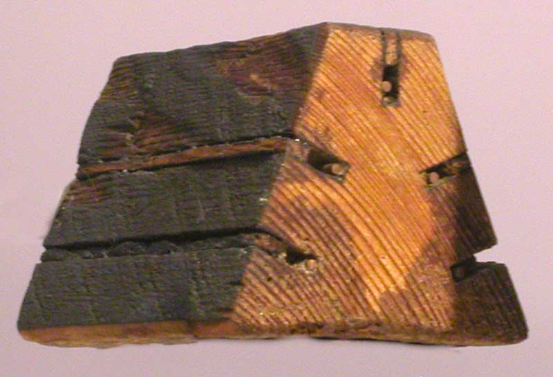
of 1850 The descriptions given below of these "cables" of 1850 are included not merely to annotate the museum specimens but also as a possible guide for Bengali industrial archaeologists looking for traces of India's first working telegraph. The three almost independent "innovations" or introductions of telegraphy in the U.S.A. (Morse), Britain (Cooke and Wheatstone), and India (O'Shaughnessy) offer valuable data for any study of the implementation of inventions in different societies and economic contexts. In some ways the introduction of telegraphy in India offers an early model of "intermediate technology" whereby European knowledge and apparatus were adapted creatively to local craftsmen and materials. The background for such a study is furnished by Mel Gorman's well-documented article on the work of (Sir) William Brooke O'Shaughnessy (1809-89), published in 1971 (note 31), as well as studies on early Indian telegraphy by Saroj Ghose of the Birla Museum, Calcutta, which are now being eagerly waited for in Europe. The Science Museum's specimens of the half-pipe (or tile) conduits used in India (note 32) by W.B. O'Shaughnessy in 1850-1 represent two separate accessions:
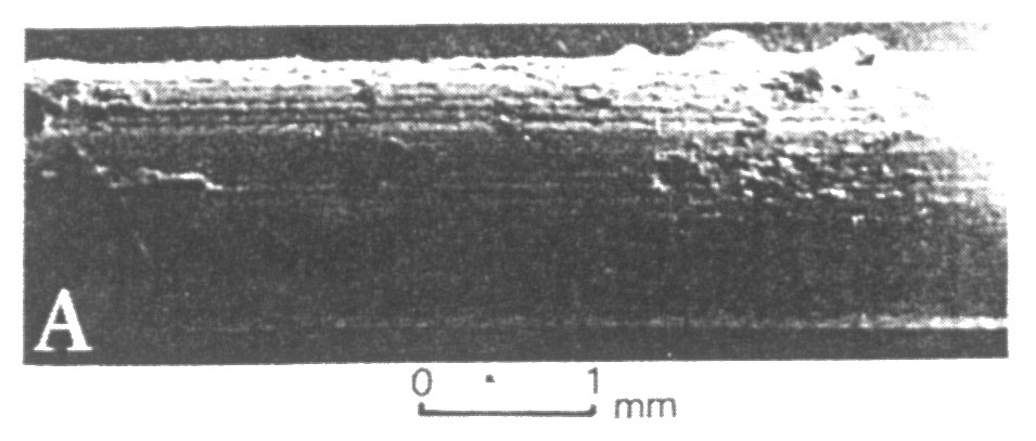
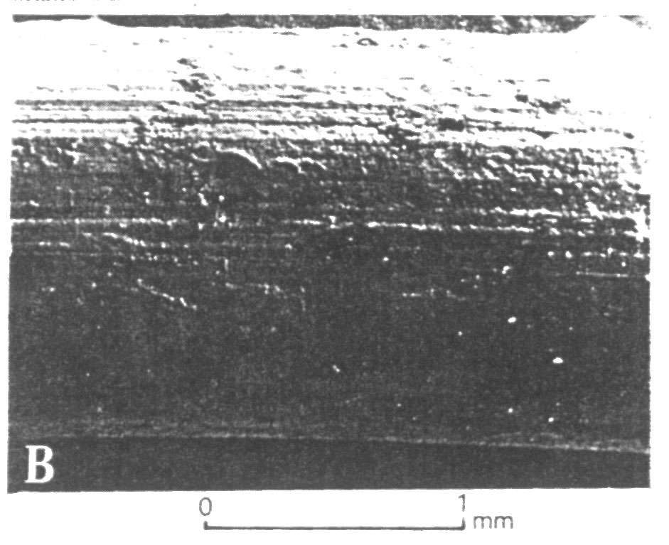
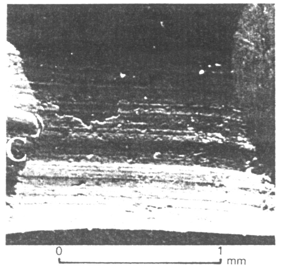
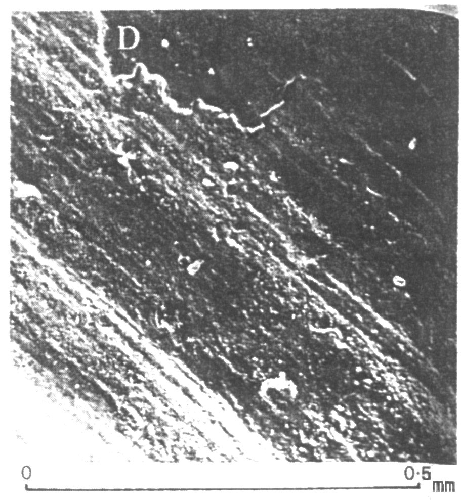
The two accessions represent different types of half-pipe, but they can both be regarded as forms of local pantiles for roofs, made in a pinkish earthern-ware. These tiles are filled with what looks like a mortar that appears in some examples to be tarry. The "wire" of the specimen illustrated in Fig. 9 is a rod of iron 9.60mm (c.0.38 in. or c.380 mils) in diameter with a cloth and pitch jacket about 1 to 2mm thick. The similarly arranged wire in Fig. 10 is 9.90mm in diameter (c.0.390 in. or c.390 mils). It is clear that the gauge of the wire is much larger than those of British or later Indian No. 1 gauge wires. We know that the "wires" were regarded as rods and that the diameter was 3/8 in. (or 0.375 in.). It is possible that the rods were manufactured in England (note 33). Tar or pitch seems to have been used in some pieces for joining a collar into the larger end of the next half-pipe. Some pipes are liberally painted with tar inside and out. The chronology of these early lines can be briefly outlined as follows. After preliminary delays when, for example, labour was not available because of festivals, works consisting of sheds and forges were set up between 10 October 1850 and 1 November 1850. The first underground mile was buried with "double conductors" by 5 November (note 34). Progress was rapid and some telegraphic communications were established between Alipore (then outside Calcutta) and the Semaphore Tower at Diamond Harbour by 24 December 1850. Most of this preliminary line (totalling 26 3/4 mi.) was on bamboo stakes (note 35). O'Shaughnessy began by laying down the conductor embedded in buried "half-pipes as far as "Rajhat", a little rice-trading village some fifteen miles south of Alipore, which was reached on 7 February 1851. Place-names can be very uncertain even for that well-studied part of Bengal but there is no doubt that this place was the one later recorded as "Rajahat" or "Rajar Hat" (note 36). The Science Museum conduits are almost certainly from between Alipore and "Rajar Hat". At the latter place was set up a "mud Bungalow with tiled floor and glazed windows", used for testing the line during the season of rainstorms. O'Shaughnessy then ran the next section of twelve miles to Diamond Harbour without the half-pipes to hold the rods and without the rosin and sand used to embed the wire. This simplified system was to work quite well and one might see considerations of effective technical design being brought forward. But O'Shaughnessy's comments reflect a different reality! "Having reached this point Rajhat the stock of rosin in the Calcutta market fell short and the price rose so excessively that I did not consider it proper to proceed at once to extend this system of construction further from that point I accordingly determined to make trial of the cloth and pitch envelope alone using a third coating." (note 37). Because of this O'Shaughnessy buried, for the twelve miles between Rajhat and Diamond Harbour, his rods wrapped in cloth and pitch only. He cheerfully put down his line in muddy waterlogged trenches, reassuring himself with periodic test messages sent along the rods which in some stretches were laid in what was little more than mud. Since it is probable that the examples in the Science Museum are from the Alipore-Rajhat stretch all other extensions are strictly outside the scope of this study. But a few brief remarks should be made about the system completed 8 March 1851. He also ran an underground line from "Sursya" near Diamond Harbour, to "Kholakhali", a distance of 4 3/4 miles (note 38). In May 1851 a branch was extended from Bishtopur (=Bishnupur or Vishnupur) (note 39) to Mayapur on the banks of the Hooghly. By the end of the summer an extension was set up on the other bank between Kukrahati and "Kedgeree" (Khejri or Khajuri) and by March 1852 an underwater line, using gutta-percha-covered cable protected by a chain (note 40), was across the Hooghly. Although the original line was said to begin at Alipur or Alipore, O'Shaughnessy was later to report (note 41) that ultimately his completed underground line began at "Chandpal Ghaut", which is Chandpal Ghat, near the High Court in Calcutta, and went through the Maidan and past the racecourse, over the "Alipore Bridge" (near the Jail and Bhawanipur) "through the populous bazars and suburbs of Alipore, Bursia and Beyla" ( presumably Barisa and Behala) (note 42), and "through the Mission station of Thakoorpookur" (now Thakurpukur). The underground conduit then went on to "Rajmoola Chucka village, on the causeway, where the ground system commences". Rajumullah is on the west side of the causeway which begins a mile to the north, but the 1866 ordnance survey sheet (note 43) has Ck (i.e. Chak) Rajumulah to the east of the causeway. All possible places that an industrial archaeologist might want to trace have been listed. The next task is to outline the physical details of the cable. The 3/8-inch rod iron was supplied in lengths of 13½ feet and welded at the Iron Bridge Works at Alipore into lengths of 200 feet. Carried along in bundles of ten, the rods were welded together at portable forges operated by "native blacksmiths" under a European sergeant (note 44). The rod weighed an average of 1,939 lb (879.5 kg) per mile (note 45). Not all of O'Shaughnessy's line was underground. Bamboo poles of various heights were used to support the rods, a source of ineffable delight to local monkeys. The system was able to survive hurricanes. C.C. Adley later calculated that at one time some 69 miles of the system was overground and 11 miles buried in trenches (note 46). It is also known that a Sergeant Smith, at the head of a team consisting of a boatswain (tindal) and twenty boatmen (lascars), laboured at wrapping round the rods several layers of Madras Cloth (cotton) (note 47) soaked with melted pitch softened with tar (note 48) at a rate of 2,000 feet a day. For a particular stretch at least they supported the rods on bamboo stakes three feet above the ground (note 49), a measure that later enabled the line to survive the attentions of elephants. Sergeant Anderson with two native inspectors and "50 workmen on high wages" were in the meanwhile engaged in embedding other sections of the wire in the row "of thin roofing tiles, of semi-cylindrical form (the koprile, of Bengal)" (note 50). The mixture used by Sergeant Anderson and his colleagues consisted of carefully sifted, washed and dried sand proportioned by weight of three parts to one part of rosin (note 51). One can visualize the activity and the mess as the workmen melted together the sand and rosin in kuroys (iron bowls) over temporary roadside fire-places. O'Shaughnessy regarded the work as tedious, but it was possible to deal with some 1,300 to 1,700 feet per day (note 52). Long-handled iron ladles were used to half-fill the pipes holding the rods. Then, at the next stage, more of the mixture was poured in. Despite the vivid detail regarding the putting down of these conduits into a 2-foot trench beside the metalled road, one cannot say today whether the curved tiles were convex-side-up or convex-side-down. One guesses that convex-side-down tiles were easier to fill. Whatever may be our uncertainties about interpreting the evidence above there is no doubt that the system functioned very well. As O'Shaughnessy said in an excellent little handbook he produced in 1852: ". . . the insulation of this line is excellent, and its mechanical solidarity perfect; but its retention of' the electric charge . . . renders it inapplicable to the construction of long lines. For short special lines - say of ten miles - unconnected with any long circuits, the plan presents several advantages - not the least of which is the faculty with which all the materials are procurable in most of the native bazaars (note 53). Acknowledgements It should be pointed out that though most of the wires and cables described in this article were on display in 1978 at the Science Museum, some of them might subsequently be put in store. In any case earnest students of the subject are urged to giver several days' notice to the museum before a visit, since stores are outside London. Appendix. Two small pieces of the uncovered wire were examined with an electron scanning microscope (see Plates A, B, C, D). The striations produced when the wire passed through the die showed up very clearly and certain possibilities can be seen for the future investigation of ancient wires. One line of investigation would be to see whether a wire has been "killed", that is, stretched slightly by a system of rollers to ensure better handling in the field as well as for detecting weak points. This is thought to have been introduced by C.F. Varley some time before 1854. One has learned the need to clean the wire of traces of gutta-percha before coating it for the microscope by "sputtering"! Next time, benzene will be tried. It is hoped that other workers may be tempted to join me in investigating other features of the wire, such as conductivity.
|
|
Last revised: 31 January, 2010 |
|